
Robot Proximity Sensor Schematic

The Proximity Sensor circuit employs the GP2Y0A21YK IR Sensor, which operates by emitting infrared light and measuring the amount of light reflected back from nearby objects. This sensor provides a voltage output proportional to the distance of an object, facilitating the detection of obstacles within a specified range. The analog output from the sensor is fed into the PIC's analog-to-digital converter (ADC), where it is transformed into a digital signal. This digital signal can then be processed by the microcontroller to determine the proximity of objects.
The inclusion of a headphone speaker enhances the circuit's interactivity, allowing the robot to produce sound feedback. This feature can be programmed to activate under certain conditions, such as when the proximity sensor detects an object within a predetermined threshold. The software controlling this function can be designed to generate a simple tone or a more complex sound pattern, effectively communicating the robot's status to nearby observers.
The addition of LEDs serves as a visual feedback mechanism. The circuit can be designed such that the red LEDs illuminate when the proximity sensor detects an object within a critical distance, signaling that the robot is in a potentially hazardous situation. Conversely, the blue LEDs may be programmed to light up under conditions that indicate the robot is operating normally or is in a "happy" state, such as when it is not detecting any obstacles.
In summary, this Proximity Sensor circuit combines various elements to create an interactive system that not only detects nearby objects but also provides auditory and visual feedback to enhance user understanding of the robot's operational status. The integration of the IR sensor, headphone speaker, and LEDs contributes to a comprehensive approach to proximity detection and response, making it suitable for applications in robotics and automation.The Proximity Sensor circuit can be seen below. Three red boxes show the additions to the circuit that we already built in Part 2: Motor Control. The new parts used and seen in the schematic below are the GP2Y0A21YK IR Sensor, Headphone Speaker and some LEDs. The analog voltage (between +3. 5v to +0. 0v) is input into the PIC`s AN0, Pin 1 which is the analog to digital converter on the PIC. This means the PIC can then convert that analog output into a digital integer that we can evaluate and use it to make intelligent decisions. Just for fun, we`ll add a headphone speaker so that the robot can `scream` to warn off anything that gets too close to it.
This really just means a little extra software, and it`s a fun way to give some extra output that humans definitely understand. We`ll also grab some LEDs from our assorted LEDs bag and put them into the circuit to give us feedback.
Red LEDs will turn on when the proximity sensor detects something that is `too close for comfort` and blue LEDs will represent when the robot is happy. 🔗 External reference
Related Circuits
This is the circuit diagram of a line follower/line tracker robot. The circuit is derived from tutorial documentation, which can be downloaded at the end of this article. The line follower robot utilizes eight proximity sensor modules. Each sensor...
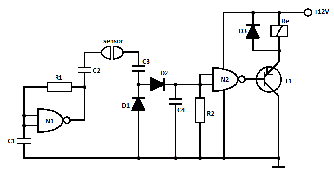
This is a straightforward liquid detector that utilizes a relay to activate an evacuation mechanism. It can be employed for water or any liquid that conducts electricity. Any PNP transistor capable of handling the relay current can be used....
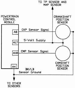
AutoZone Repair Guide for Engine Performance and Emission Control Components and Systems, specifically focusing on the Camshaft Position Sensor. The Camshaft Position Sensor (CMP) is a critical component in modern internal combustion engines, playing a vital role in the management...
The working voltage of capacitors C1 and C2 should be increased to 25V if a 12V power source is used. A general guideline is that the operating voltage of capacitors should be at least double the supplied voltage; for...
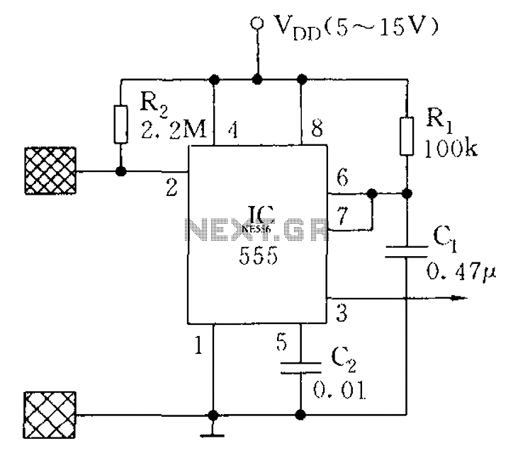
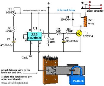
The proximity switch using the 555 timer functions as a monostable trigger circuit. The trigger pin (Pin 2) of the 555 timer is connected through a large resistor (R2) to the positive supply voltage (VDD) and is in a...

The power output of most of these circuits is very low because no power amplifier stages were incorporated. The transmitter circuit described here includes an additional RF power amplifier stage, following the oscillator stage, to increase the power output...