
Current spreading circuit diagram of a bipolar output

The circuit described involves a current spreading bipolar output configuration. This type of circuit is typically used in applications requiring efficient current distribution across multiple output paths, often seen in power amplification and driving loads in electronic systems.
In a current spreading bipolar output circuit, bipolar junction transistors (BJTs) are utilized to achieve the desired output characteristics. The circuit design may include a differential input stage that amplifies the input signal and drives the output stage composed of multiple BJTs configured in parallel. This configuration allows for the sharing of current among the transistors, thereby improving reliability and thermal performance.
The circuit diagram may feature a biasing network that ensures the transistors operate in their active region, preventing cutoff or saturation during signal processing. Resistors may be employed for emitter degeneration to improve linearity and stability, while capacitors can be included for AC coupling or bypassing to filter out noise.
The output stage may be designed to drive various loads, such as speakers or other electronic components, with the ability to handle significant current levels. Feedback mechanisms could be incorporated to enhance the performance by reducing distortion and improving frequency response.
Overall, the current spreading bipolar output circuit is a robust design choice for applications demanding high performance and efficiency in current handling.Current spreading bipolar output when the circuit diagram is as follows:
Related Circuits
The following circuit illustrates a Bass-Treble Tone Control Circuit electronic diagram based on the LM1035N integrated circuit (IC). Features include a 0.3 Vrms input level, 80 dB signal noise ratio, 75 dB volume control, ±15 dB typical tone control,...
Lamp dimmer. The circuit illustrated below can be employed for dimming lamps. It utilizes a minimal number of components, which can be conveniently installed within the lamp socket. This circuit is typically utilized in RC phase shift configurations. The...
Grounding the blue wire at the headlamp switch causes the lights to illuminate, indicating a faulty switch. Continuity of the switch has already been verified. The relay consists of two small terminals and two larger ones. The smaller terminal,...
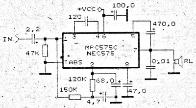
An amplifier circuit is particularly well-suited for use in confined spaces, such as within vehicles. It requires a voltage supply ranging from 9 Volts to a maximum of 17 Volts. This amplifier circuit utilizes the IC MPC575C, which is...
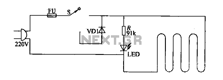
The circuit of electric blankets is controlled by switch S. When switch S is fully engaged, the entire supply voltage of 220V is applied to the heating wire, resulting in a high-temperature state. When a lower temperature is desired,...
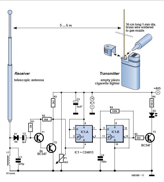
In 1896, Marconi successfully transmitted electromagnetic waves over a distance of approximately 3 kilometers. Shortly thereafter, he established radio communication across water between Lavernock Point in South Wales and Flat Holm Island. The transmitter utilized a spark inductor connected...