
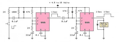
Triggering a 555 with another

The monostable 555 timer circuit is a versatile component widely used in timing applications. In a monostable configuration, the 555 timer produces a single output pulse in response to a triggering event, which can be an external signal or a manual switch. This output pulse duration is determined by the resistor-capacitor (RC) timing network connected to the timer.
When considering the output of one monostable 555 timer circuit as a trigger for another similar circuit, it is essential to analyze the characteristics of the output signal. The output of the first timer is typically a square wave pulse, which can be used to trigger the second timer circuit's input. The second 555 timer can be configured in monostable mode to generate its own pulse in response to the trigger received.
To ensure proper operation, the output voltage level of the first timer must be compatible with the trigger input of the second timer. The 555 timer outputs a high state close to the supply voltage when triggered, and this should be within the acceptable input voltage range for the second timer. Additionally, the pulse width of the output from the first timer should be sufficient to reliably trigger the second timer. It is advisable to design the timing parameters of the first timer to accommodate the trigger requirements of the second timer.
In summary, the output of a monostable 555 timer can indeed be used to trigger another similar timer circuit, provided that the output characteristics align with the input requirements of the second timer. Proper consideration of voltage levels and timing parameters will facilitate the successful cascading of multiple 555 timer circuits in a design.Can anybody tell me if the output of a monostable 555 timer circuit can be used to trigger another similar timer circuit. I have shown my idea with a.. 🔗 External reference
Related Circuits
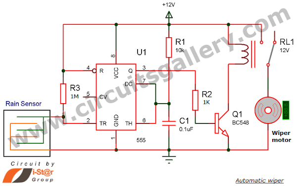
Have you seen Audi, Lexus, or Ford rain-sensing wipers and wondered how they operate in these vehicles? They are controlled by sensors located at the center of the windscreen, which detect raindrops and activate the wiper motor. The functioning...
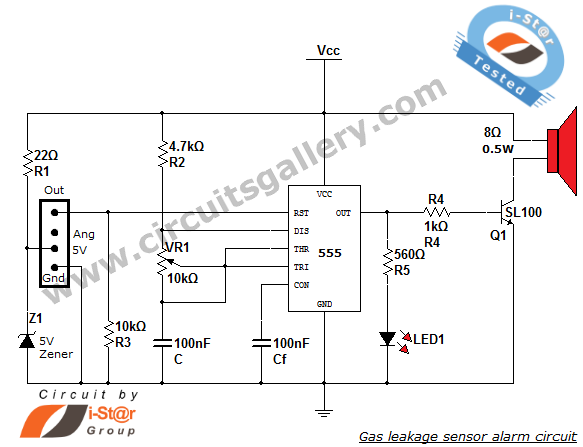
This article discusses a home security alarm circuit designed to detect LPG gas leakage. The circuit utilizes a gas sensor module, SEN 1327, which incorporates a QM 6 gas sensor. The output signal from this gas sensor module is...
The LM555 timer circuit is similar to the previous design but incorporates two stages, allowing for control over both the pulse width and the delay. The LM555 timer is a versatile integrated circuit widely used in various timer, delay, pulse...
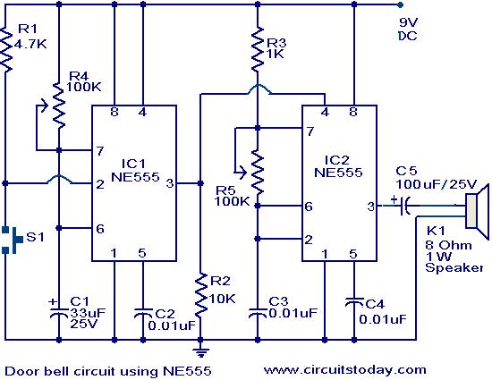
The primary components of this doorbell circuit are two NE555 timer integrated circuits (ICs). When switch S1 is pressed momentarily, the loudspeaker emits a bell tone for the duration determined by the monostable multivibrator configuration around IC1. Pressing switch...
This circuit is straightforward. The initial 555 timer prevents the second timer from being activated while the first is operational. Drive the circuit with a simple 12-volt power supply. The circuit utilizes two 555 timer integrated circuits (ICs) configured in...
When the phototransistor is struck by IR light, it conducts, and the voltage between the 1 MΩ resistor (arbitrary) and the phototransistor drops from VCC to lower values. When the voltage drops lower than VCC/3, the 555 is triggered...