
CW Transmitter 5 Watt

This circuit represents a straightforward 5-watt Continuous Wave (CW) transmitter utilizing a TTL logic chip, specifically the SN7400. The design hinges on a critical component, Cx, which is responsible for shaping the output waveform. This capacitor must possess an impedance of approximately 10 to 50 ohms at the desired operating frequency. Adjusting the value of Cx allows for control over the output power; increasing its capacitance reduces the transmitter's power output. Cx effectively smooths the square wave generated by the output transistor, resulting in a waveform that more closely resembles a sine wave.
Initial capacitance values for Cx are provided for various frequencies, indicating a range of starting points that can be adjusted based on performance needs. For instance, at 1.8 MHz, a capacitance of 4.7 nF is suggested, while at 28 MHz, a lower value of 330 pF is recommended. The component choice for the RF power transistor (TR1) is flexible, with any RF transistor capable of handling at least 800 mA being suitable for this application. The BC108 is mentioned as a potential option, though it limits output power to around 150 mW when used with a higher value of Cx.
The output stage of the transmitter employs a tuned circuit without a ferrite slug. The design utilizes a rule-of-thumb approach for determining the coil and capacitor values, linking them to the wavelength in meters. The output winding of the coil should encompass 5% to 15% of the total number of turns, requiring adjustment to optimize power output before finalizing the value of Cx.
Powering the circuit involves supplying +5 volts to the SN7400 chip while delivering +12 volts to the power amplifier (PA), resulting in an output exceeding five watts. To activate the transmitter, a keying mechanism is integrated into the +12V lead. It is crucial to implement an antenna low-pass filter (LPF) when using a high-quality antenna, although this may not be necessary for tuned antennas such as magnetic loops. Caution is advised against using a linear amplifier with this transmitter design. The compact nature of the finished transmitter allows it to be housed in a matchbox, facilitating portability and ease of use.This is a very simple 5 watt CW TX based upon a TTL logic chip. There is just one "tricky" component and this is Cx. This component should have an impedance of about 10 - 50 ohms at the frequency of interest. If you wish to reduce the transmitter power, increase the value of Cx. It is Cx which causes the square wave from the output transistor to approximate a sine waveform. The value of Cx is the price of simplicity in this TX. STARTING values for Cx are as follows (but there is a LOT of leeway) 1.8 MHz = 4.7nf 3.5 MHz = 2.2nf 7.0 MHz = 1.2nf 10 MHz = 820pf 14 MHz = 560pf 18 MHz = 470pf 24 MHz = 390pf 28 MHz = 330pf It is far better to use too high a value for Cx initially then reduce it to achieve the correct RF output power. The value of Cx will depend upon your choice of TR1. Virtually any RF power transistor will work well in this application, as long as it will handle 800mA continuously.
I have even used a BC108 in this application but the RF power was restricted to about 150mW. Cx was about 5x the value quoted above. The output tuned circuit uses a coil WITHOUT ferrite slug. Use the usual "rule-of-thumb" formula for the tuned circuit; Coil = Wavelength (in meters) = number of turns Capacitor = Wavelength (in meters) = Capacitance (pf) This will get you in the right area although it could differ widely with different coil formers. The coil output winding is from 5% to 15% of the total number of turns. Adjust the output winding before reducing the value of Cx. You need the least number of turns that will give you the power needed. Connect +5 volts to the SN7400 chip and +12 volts to the PA and you will have over five watts of power out.
To key the TX put the key in the +12v lead. You MUST use an antenna LP-filter with this rig if you are using a good antenna. If the antenna is tuned (magnetic loop or frame antennas etc) then you need not bother with the LP-filter. Do NOT use a linear amplifier for this transmitter. The finished transmitter will fit into a matchbox with a little care. 🔗 External reference
Related Circuits
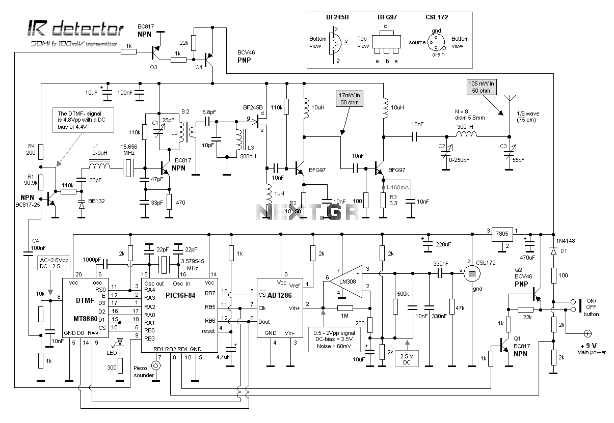
This project is about an IR-detector (Infra Red) combined with a 100mW 50MHz transmitter. The detector is sensitive to changes in IR-spectrum and is commonly used in burglar alarms. When the detector senses a person/animal/ghost/angry clown, it will transmit...
L1 and L2 are copper wires with a diameter of 0.4 mm, wrapped in a plastic support with a diameter of 6-7 mm, featuring a perjstrofjkoy core. For L1, 13 coils are wrapped, while for L2, 4 coils are...
The following circuit illustrates an audio amplifier circuit diagram with a power output of 25 watts. Features include its widespread use in nearly all mass-market stereo receivers produced, providing enhanced sound quality. This audio amplifier circuit is designed to deliver...
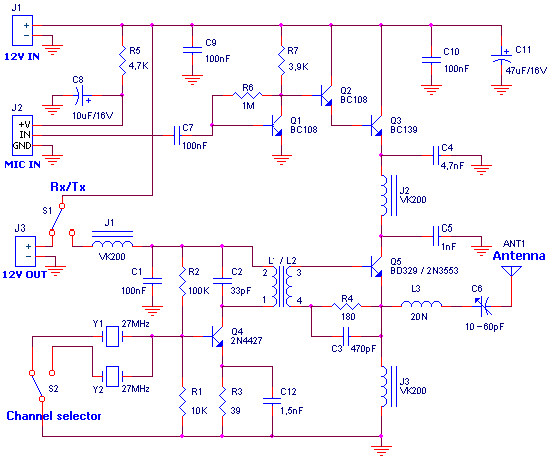
This ZIP file contains information about building a small radio transmitter, which has a PCB 1.75" x 2.5" (45mm x 68 mm) and has a range of about 30 yards or so. The documentation with the circuit says the...
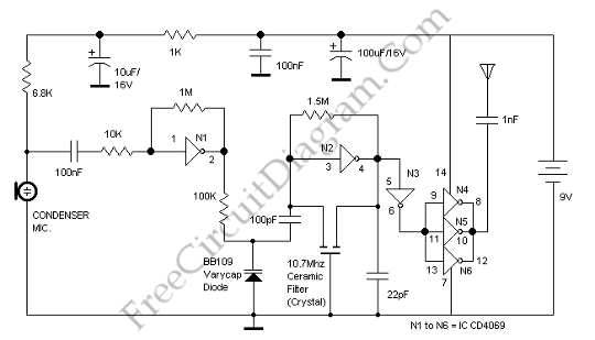
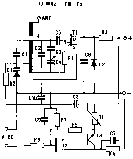
This is an FM transmitter circuit that utilizes logic gates. The circuit features a radio frequency (RF) oscillator, which operates with a 10.7 MHz ceramic filter. The FM transmitter circuit is designed to modulate audio signals onto a carrier frequency...
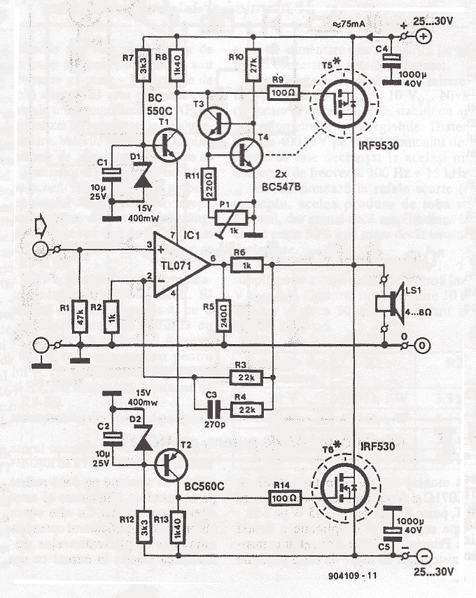
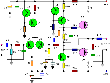
This simple power MOSFET audio amplifier circuit utilizes a TL071C operational amplifier and two MOSFETs (IRF9530 and IRF530), capable of delivering up to 45 Watts to an 8-ohm speaker. The schematic is based on a Siliconix application and incorporates...