
DAC with WM8740
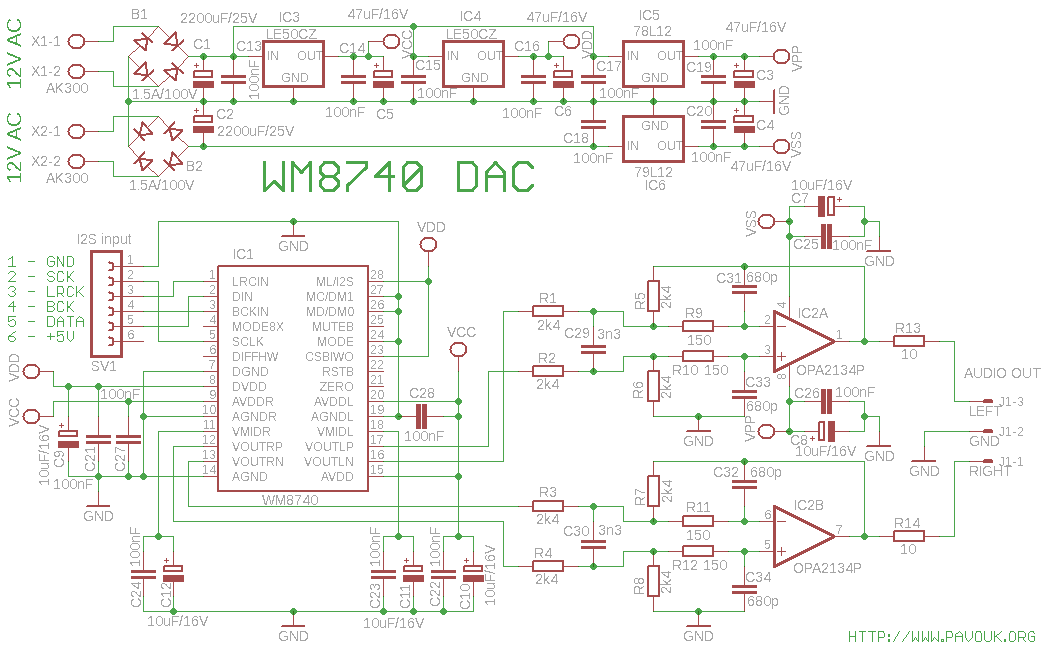
For powering the analog and digital components of the DAC, low-dropout voltage regulators, specifically LE50, are utilized. The operational amplifier is supplied using common 78L12 and 79L12 voltage regulators. A transformer with dual secondary windings rated between 12 to 15V is required. The winding for the positive supply branch (AC1) can be connected in parallel to the S/PDIF decoder if an individual winding is not available. All voltage regulators are adequately decoupled with 100 nF ceramic capacitors, and the outputs are filtered with 47 µF/16V electrolytic capacitors. The DAC and operational amplifier also have all supply pins decoupled in accordance with the datasheet, using 100 nF ceramic capacitors and small 10 µF/16V electrolytic capacitors. The DAC is configured in hardware mode using the MODE pin, allowing settings to be adjusted by setting the appropriate pins to logic levels 0 or 1. The pins CSBIWO and ML/I2S are used to configure the data format for I2S/24-bit, which is widely supported by S/PDIF decoders and USB sound cards that output I2S.
The DAC features balanced voltage outputs, which connect to a second low-pass filter utilizing a dual operational amplifier with very low distortion, specifically the OPA2134. This amplifier also converts the balanced output to an unbalanced signal. The filter schematic is derived from the AK4396 datasheet. A small resistor is placed at the output to prevent oscillations when connected to non-ideal loads. No coupling capacitor is required at the output if the components are properly selected. Measurements indicate a DC offset voltage of 1.9 mV on one channel and zero on the other. The DAC performs optimally upon initial connection, exhibiting a balanced sound profile without interference. The output waveform, analyzed using an oscilloscope, meets expectations for a DAC employing oversampling and delta-sigma modulation, showing pre-ringing and post-ringing characteristics.
An additional filter is available in software mode to mitigate pre-ringing, which enhances sound quality, although this feature is not accessible in hardware mode. Testing was conducted in two configurations: System Clock at 128FS and 256FS. The 256FS mode exhibited significantly greater pre- and post-ringing, while the 128FS mode demonstrated improved performance. According to the datasheet, in the 128FS mode, the first stage of the digital filter is bypassed. This mode supports all standard sample frequencies ranging from 44.1 kHz/16-bit to 192 kHz/24-bit and is also compatible with USB sound cards with I2S output. It is recommended to set the system clock to 128FS when interfacing with S/PDIF decoders or other data sources utilizing I2S output.
In comparison to R-2R DACs lacking oversampling and output filtering, this DAC produces less clarity at high frequencies but offers reduced stress on sound production, which may be a subjective preference. The sound quality is exceptional, with the choice of DAC ultimately depending on personal preferences and budget considerations. The manufacturing cost of this board is approximately five times lower than that of a board featuring two PCM1704 DACs.It is high performance DAC with oversampling, delta-sigma architecture and maximum sample frequency 192kHz/24bit. It has balanced voltage output. It is connected to high-quality operational amplifier which has low-pass filter function and buffer with single-ended output.
Board also includes complete power part of circuit except transformer. In supply part I used two bridge rectifiers similar to other my dac boards. For supplying of analog and digital part of dac I used low-drop voltage regulators LE50. For supplying of operating amplifier I used common 78L12 and 79L12 voltage regulators. We must use transformer with two secondary windings with 12 to 15V. Winding for positive supply branch AC1 can be paralelly connected to S/PDIF decoder when we haven`t individual winding for them. All voltage regulators are properly blocked with ceramic capacitors 100nF and on the output filtered with electrolytic capacitors 47uF/16V.
DAC and operational amplifier have also blocked all supply pins according to datasheet with ceramic capacitors 100nF and small electrolytic capacitors 10uF/16V. DAC is set to HARDWARE mode with pin MODE. It means, that settings are changed with setting right pins to LOG 0 or 1. With pins CSBIWO and ML/I2S is configured data format for I2S/24bit. This format is most common and is supported on all S/PDIF decoders and USB soundcards with I2S output.
DAC has balanced voltage outputs. To them is connected 2nd low-pass filter with dual operational amplifier with very low distortion OPA2134. This amplifier simultaneously converts balanced output to unbalanced. Schematics of filter is adopted from AK4396 datasheet. On the output is connected small resistor which could prevent oscillations when not ideal load is connected.
The output doesn`t need coupling capacitor, when parts are properly selected. I measured DC-offset voltage 1. 9mV on one channel and zero on another. DAC works perfectly on the first connection. His sound is strain with balanced characteristics without any interference. I checked the output waveform with a oscilloscope and it looks exactly to my expectations for DAC with oversampling and delta-sigma modulation. His response to unit impulse or square wave has preringing and postringing. This dac have another filter which eliminate preringing which is good for sound, but it is available only in software mode.
I tested two variants with System clock 128FS and 256FS. In 256FS mode output has much bigger pre and postringing. In 128FS mode it is much better. In datasheet is information, that in this mode is first stage of digital filter bypassed. 128FS mode also supports all common sample frequencies from 44. 1kHz/16bit to 192kHz/24bit and is also supported on USB soundcards with I2S output. I recommend to set system clock to 128FS on S/PDIF decoders or other data sources with I2S output. Against to R-2R DACs without oversampling and without output filter is sound on high frequencies a fewer clear but it is a less stress. It is probably very subjective. His sound is excellent and it is only about personal preferences and money which DAC to select. Also price of manufacturing of this board is about five times cheaper than price of board with two PCM1704 DACs.
🔗 External reference
Related Circuits
A transformer with two separate 12V secondary windings is required for the power supply. If the transformer does not have a third separate winding, the supply input of the S/PDIF decoder must be connected in parallel to the positive...
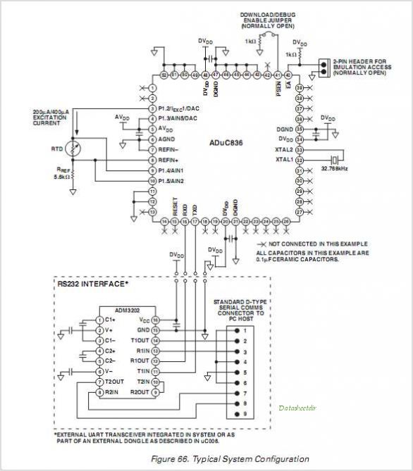
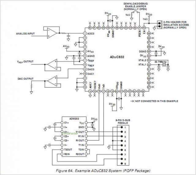
The ADUC841, ADUC842, and ADUC843 are complete smart transducer front ends that integrate a high-performance self-calibrating multichannel ADC, a dual DAC, and an optimized single-cycle 20 MHz 8-bit MCU (compatible with the 8051 instruction set) on a single chip....
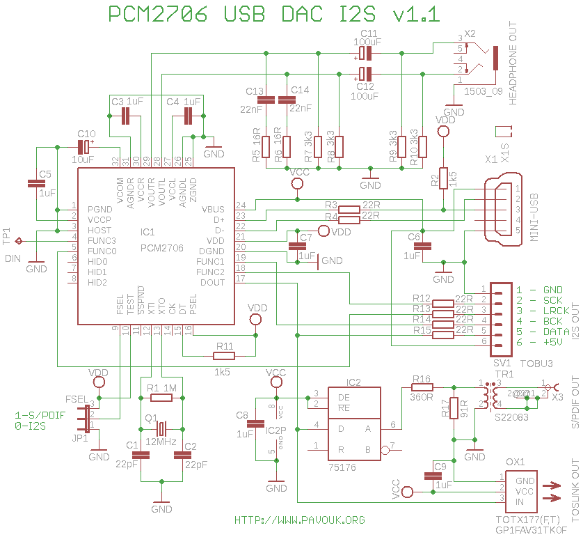
This project involves a couple of USB Digital-to-Analog Converters (DACs) that lack I2S output. Some users do not require S/PDIF input and prefer a direct USB connection. Therefore, it is unnecessary to convert the signal from USB to S/PDIF...
The ADUC831 MicroConverter is a fully integrated 12-bit data acquisition system-on-a-chip. Like all of Analog Devices Inc.'s MicroConverter products, it features precision A/D and D/A conversion along with a Flash Microcontroller on a single chip. The ADUC831 is fully...
The idea behind the portable DAC is to get better sound than from the line out or headphone out of portable CD player, a pc sound card or other digital audio source. Many of us want to listen to...
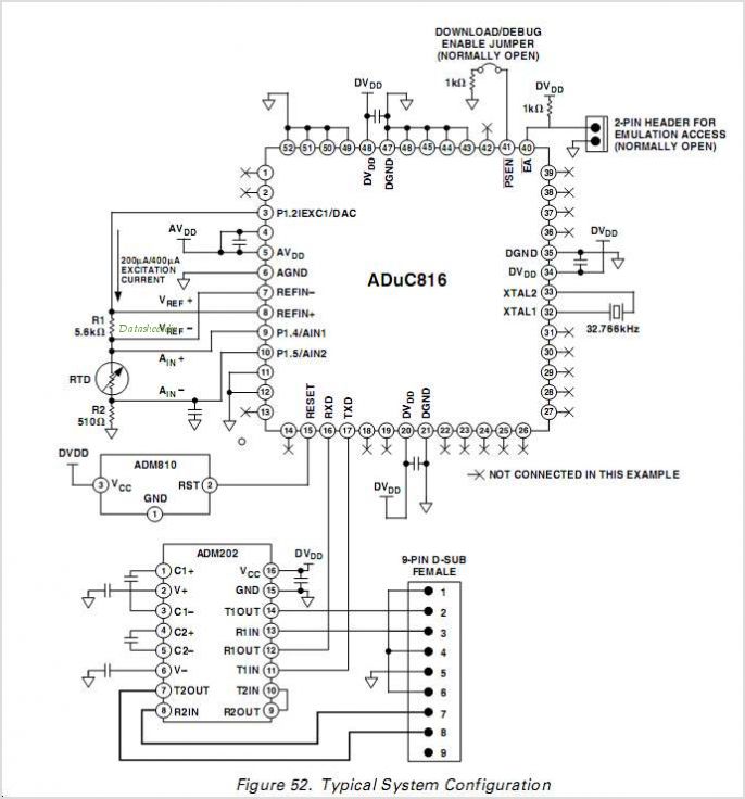
The ADUC836 MicroConverter is a fully integrated 16-bit data acquisition system-on-a-chip. Like all of ADI's MicroConverter products, it features precision A/D and D/A conversion along with a Flash Microcontroller on a single chip. The ADUC836 is fully backward compatible...