
Reflex Game using MC9S08QG4
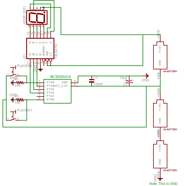
The circuit design for this game leverages the Freescale MC9S08QG4 microcontroller, which is well-suited for handling the input and output requirements. The microcontroller's two pins connected to the light switches allow for quick detection of player inputs. The use of pull-down resistors ensures that the inputs remain stable when the switches are not activated, preventing erroneous readings. The 74LS47 display driver is crucial for converting the binary signals from the microcontroller into a format suitable for the HDSP-5551 7-segment display, which visually communicates game status to the players.
Power management is effectively handled with the choice of capacitors, which provide stability to the microcontroller's operation. The circuit's design is optimized for responsiveness, ensuring minimal latency between player input and display output. The microcontroller's firmware is responsible for managing the game logic, including the randomization of game modes and the timing of the countdown. This design exemplifies a straightforward yet effective approach to creating an engaging electronic game that relies on rapid player reactions, incorporating both hardware and software components cohesively.When the display reads "0", players turn on their light switch as quickly as possible. Whichever player turns on their light switch first is the victor. Don`t get the wrong impression-the display doesn`t go to "0" right after the "3" "2" "1" countdown-this only happens once in a while when all the random conditions are met. The game is completely random and shifts between different "game modes"-counting up and down (by 1 and 2) and random numbers. It can do all of these in a normal or fast speed. It can do these with a certain chance of randomly going to zero, or going to zero after the "game mode" is finished. A random number of game modes are chosen and initialized (randomly) before the game starts. The game modes each can be repeated a certain number of times. The game modes are then iterated over in a random order. Games usually run from 15 seconds to 5 minutes. Some people enjoy the short games lasting 15 second or less-especially me-while others enjoy the wrenching games up to 5 minute long.
Entropy is introduced (and used in subsequent calculations) by the time difference between a player turning on the game and flipping a light switch. An example game: The game is built around the 8-bit Freescale MC9S08QG4 microchip. Two pins on the MC9S08QG4 are wired (with pull-down resistors) to two light switches which provide the necessary input from players.
Three other pins are wired to the inputs of a 74LS47, driving the display. I was too lazy to wire the extra pin to the display or provide support for a third player. I wrote the firmware for the MC9S08QG4 using the supplied Freescale Codewarrior in C and assembly. An off-track note about Codewarrior: It`s not actually suited to editing code. It can`t auto-tab correctly and auto-complete isn`t functional-not that I needed autocomplete for this project. I usually edited code with jEdit then copied & pasted it to Codewarrior. It`s other features like Device Initialization and work-the-first-time-I-plug-it-in are fantastic, though!
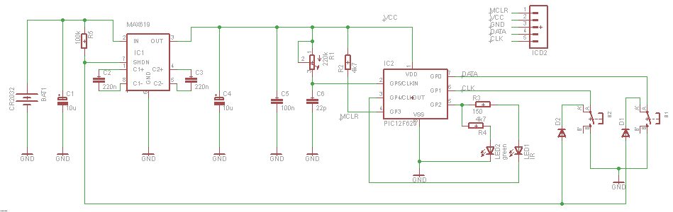
The above circuit diagram and ensuing custom parts library were made with Eagle CAD -the free version. It was made after I actually built, wired, and tested everything-which explains why I forgot the "on" switch.
Many people-from hobbyists to industry professionals-make the mistake of designing and reviewing and testing their circuits before building them-well not me! The MC9S08QG4 takes 3. 3v for power. I accomodate this difference from the 5 volt devices (74LS47 and HDSP-5551 display) by only using two of the three AA batteries (1.
5v + 1. 5v = 3v = ~3. 3v). A 100nF bypass capacitor and a 10uF bulk capacitor protect the MC9S08QG4 from fluxuations in power. I use a 74LS47 display driver to convert the binary input from the MC9S08QG4 into the decimal output for the 7-segment display. The 74LS47 does have its own 100nF bypass capacitor not shown on the circuit diagram. I use an HDSP-5551 common anode 7-segment display. The choice for the HDSP-5551 in particular was heavily biased-I already had one. I use 390 ohm resistors between the display and the 74LS47 because I had a large amount of 390 ohm resistors lying around.
Could I do better I think the displays draw around 24mA of current (No I`m not going to check the real value). 5. 5 volts / 24mA = 229. 2 ohms-yes I could do better. The switches are the standard cheap-o light switches (purchased at Home Depot). They are wired with a 10k pull-down resistor-the pins will float otherwise-to the inputs of the microchip.
Debouncing enthusiasts seeking such will be displeased-there is no need to debounce these switches. They are fairly large swithes and not connected to an interrupt-enabled pin. Plus, I do not want to wait for any debouncing business (cap charging or SR-latch computing) to occur, as this is a reflex game. I used the Device Initializer to generate most of the initialization code. I disabled the BKGND pin so that I could 🔗 External reference
Related Circuits
The AD9835 is a Direct Digital Synthesis (DDS) chip manufactured by Analog Devices. It comprises a phase accumulator, a sine wave table, and a 10-bit digital-to-analog converter (DAC). This chip can be utilized for both phase and frequency modulation...
The circuit illustrates a straightforward triangle and square wave generator utilizing a common dual operational amplifier, the LM1558, capable of producing very low frequencies around 10 kHz. The time interval for one half-cycle is approximately determined by the product...
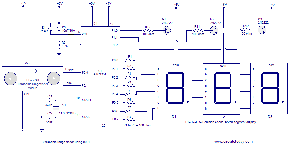
A simple ultrasonic range finder using the 8051 microcontroller is presented in this article. This ultrasonic rangefinder can measure distances up to 2.5 meters with an accuracy of 1 centimeter. The AT89S51 microcontroller and the ultrasonic transducer module HC-SR04...
The Tiny Remote is a compact infrared remote control featuring only two buttons designed to operate an iRobot Roomba. It emits three different infrared signals. The Tiny Remote is designed for simplicity and ease of use, making it an ideal...
The frequency formula of a 555 oscillator is well-known. For given resistors and capacitors, the frequency can be calculated using a specific formula derived from mathematical principles. The 555 timer IC is widely used in various applications, including oscillators, timers,...
The circuit demonstrates the application of the ZN414 integrated circuit (IC) to create a compact AM radio receiver. The ZN414 IC is a combination of a transistor and a tuned radio frequency (TRF) circuit. The ZN414 IC is specifically designed...
Warning: include(partials/cookie-banner.php): Failed to open stream: Permission denied in /var/www/html/nextgr/view-circuit.php on line 713
Warning: include(): Failed opening 'partials/cookie-banner.php' for inclusion (include_path='.:/usr/share/php') in /var/www/html/nextgr/view-circuit.php on line 713