
Automobile Interior Lights Fader circuit
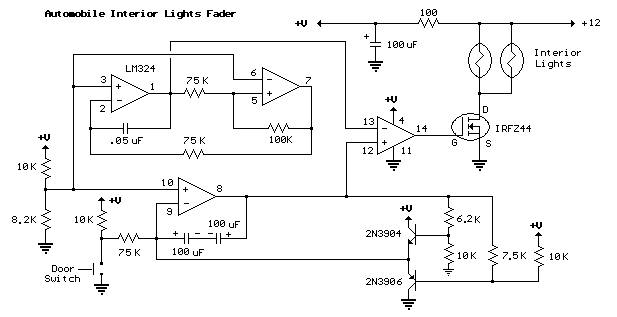
The LM324 is a quad operational amplifier, meaning it contains four independent, high-gain, internally frequency-compensated op-amps. It is particularly suited for battery-operated devices due to its low power consumption. The circuit design can leverage the LM324's characteristics to create various applications, such as signal conditioning, filtering, or amplification.
In a typical configuration, each op-amp can be used in inverting, non-inverting, or differential amplifier modes, depending on the specific requirements of the application. For instance, in an inverting configuration, the input signal is applied to the inverting terminal, while the non-inverting terminal is grounded. The gain of the amplifier can be set by selecting appropriate resistor values, allowing for precise control over the output signal.
The power supply for the LM324 can range from a single supply voltage of 3V to 32V or dual supplies of ±1.5V to ±16V, making it versatile for different applications. When designing the circuit, it is crucial to ensure that the power supply voltage is within the specified limits to avoid damaging the op-amps.
The circuit may include bypass capacitors near the power supply pins to enhance stability and reduce noise. Additionally, feedback and input resistors should be chosen carefully to ensure linear operation and prevent distortion in the output signal.
In summary, the LM324 operational amplifier circuit is effective for low-power applications, providing reliability and efficiency for battery-operated devices. Its versatility in configuration allows for a wide range of applications in electronic design.The circuit is based around the LM324 low power opamp which draws around 3mA of current, so it won`t bother the battery if left connected for extended periods.. 🔗 External reference
Related Circuits

This circuit simulates the flashing strobe lights of British police cars by alternating the lights. The IC1a functions as a square wave oscillator with an adjustable frequency controlled by VR1 to achieve the desired effect. The circuit utilizes an...
The author gifted a radio-controlled (RC) model car to his partner. She enjoyed it but suggested that adding realistic lights would enhance the experience. Consequently, the author returned to his workshop, utilized his soldering iron, and began outfitting the...
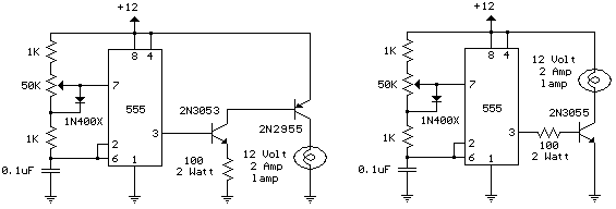
The schematic diagram illustrates a 12 Volt Car Lamp Dimmer Circuit Design utilizing a 555 Timer. This circuit can be employed to dim a standard 25-watt lamp. The 12 Volt Car Lamp Dimmer Circuit utilizes a 555 Timer in astable...

An application circuit for a biaxial magnetic field sensor is presented. This circuit utilizes the HMC1002 biaxial magnetic sensor along with two AMP04 amplifiers (A1, A2) to simultaneously measure magnetic fields in both the X-axis and Y-axis directions. The...

The following circuit is a PC thermometer utilizing the DS1621. Features include the ability to plug into any available PC COM port, a temperature range of -20 to 125°C, and the capability to display temperatures in both Celsius (°C)...

This ultra wide range timer utilizes a 555 timer as its core component, along with two 4017 decade counters and a 4020 binary counter that function as frequency dividers, which can be selectively switched in and out. Additionally, the...