
Data recieving from printer Port LTP1

The schematic involves a parallel port interface utilizing five switches, which are connected to specific input pins designated for reading digital states. The use of an external 5V power supply ensures that the input pins can achieve a high logic level when the switches are in the open position. For practical implementation, three 1.5V batteries can be connected in series to provide a voltage of approximately 4.5V, which is sufficient for this application.
To enhance the circuit's reliability, 330-ohm resistors are employed in series with each switch connection to the parallel port. This configuration offers protection against potential short circuits or erroneous connections to incorrect pins. In scenarios where the connections are verified and secure, these resistors may be omitted, allowing for a direct connection from the switches to the input pins.
The circuit's ground reference is critical; thus, the negative terminal of the power supply must be connected to the ground point of the system, which can be any of the designated ground pins (18 to 25) on the parallel port.
The accompanying QBasic program facilitates the reading of the switch states. The program is designed to interact with the parallel port at address 889, which corresponds to LPT1. It captures the state of the five input lines as an 8-bit number ranging from 0 to 255. Each switch corresponds to a specific value based on its position, contributing to the overall digital representation of the input states.
When all switches are open, the expected output should be 127, reflecting the high state of the unused bits and the active state of the switch connections. Conversely, when all switches are closed, the program should yield a value of 135, accounting for the inverted logic of pin 11. The program effectively displays the individual pin states, providing a clear output of the operational status of each switch connected to the parallel port.The diagram below shows 5 switches connected to the 5 input lines of the parallel port. An external 5 volt power supply is used to provide high logic levels to the input pins when the switches are open. Three 1.5 volt batteries in series can be used to obtain 4.5 volts which is close enough. The 330 ohm resistors in series with the port connections provide some protection in case a connection is made to the wrong pin.
If you are sure of the connections, the 330 ohm resistors can be left out and the switches connected directly to the input pins. The negative side of the power supply should be connected to the ground point, or any pin from 18 to 25.
The following short QBasic program can be used to read the state of the switches. QBASIC.EXE can be found in the "OLDMSDOS" directory of the Windows 95/98 CD Rom. Note that there are three possible printer port address that correspond to LPT1, LPT2 and LPT3 and LPT1 is usually the one to use which is at address decimal 889. The program waits for the user to press the enter key before reading the state of the 5 input lines. The state of the 5 lines is received as a single 8 bit number between 0-255 which is stored as the value of (V).
Each switch input represents a decimal value of 8,16,32,64 and 128 which correspond to pins 15,13,12,10 and 11. The last 3 bits (1,2 and 4) are not used and should return a high level, so the value received with all switches open should be 1+2+4+8+16+32+64=127.
If a switch is closed and the input is at ground, the value will be 0 except for pin 11 which is inverted and yields a value of 128 and 0 when high, so the value received when all switches are closed should be 1+2+4+128=135. ----------------------------------------------------------------------- CLS DEFINT A-Z Address = 889: REM 889 = port address, other addresses could be 633 or 957 PRINT "Press the enter key to read printer port pins (15,13,12,10,11)" PRINT "A (0) reading indicates the pin is at ground level, (1) indicates" PRINT "the pin is at a high level or unterminated." INPUT A$ V = INP(Address) PRINT V P11 = 1 IF V > 127 THEN P11 = 0: V = V - 128 IF V > 63 THEN P10 = 1: V = V - 64 IF V > 31 THEN P12 = 1: V = V - 32 IF V > 15 THEN P13 = 1: V = V - 16 IF V > 7 THEN P15 = 1 PRINT PRINT "Pin 15 ="; P15 PRINT "Pin 13 ="; P13 PRINT "Pin 12 ="; P12 PRINT "Pin 10 ="; P10 PRINT "Pin 11 ="; P11 END
🔗 External reference
Related Circuits
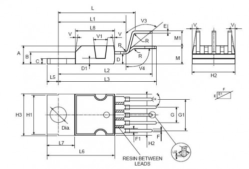
This circuit illustrates a Car Radio Audio Amplifier using the TDA2003 integrated circuit. The datasheet for the TDA2003 includes electrical characteristics and schematic wiring details. The TDA2003 is a high-performance audio amplifier designed for automotive applications. It is capable of...
Instructions for constructing a circuit on veroboard by interpreting the schematic. Experienced constructors can directly reference the schematic to begin assembly, utilizing their knowledge of component placement and efficient use of veroboard space. Beginners should have certain foundational skills,...
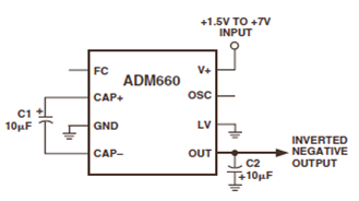
The ADM660 is a charge-pump voltage converter that can either invert the input supply voltage or double it. The schematic below depicts the ADM660 Voltage Inverter Circuit Configuration Diagram. This inverting schematic is ideal for generating a negative rail...
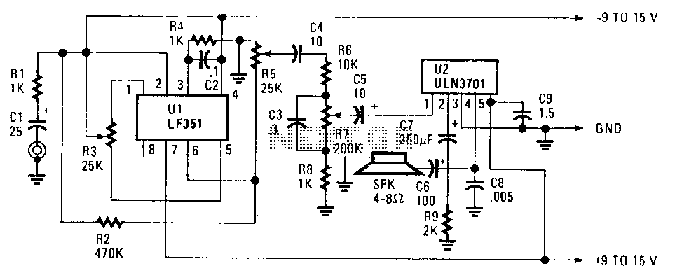
The FET operational amplifier (op amp) requires a bipolar voltage at pins 4 and 7, with a common ground to achieve optimum gain. The gain can be calculated by dividing R2 by R1. Zero-set balance can be achieved through...
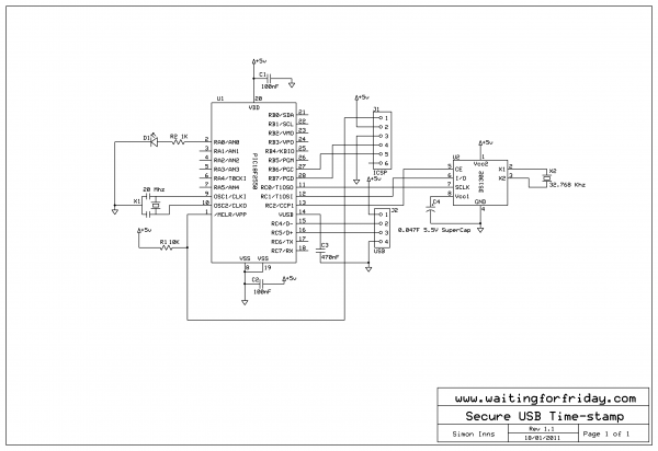
This project implements a USB device that provides a real-time clock for time-stamping events in a non-networked embedded computer environment. For embedded applications requiring periodic time-stamping (such as entry-system logs and configuration audit logs), an accurate real-time clock is...
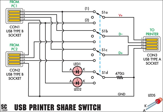
This device allows two computers to share a single USB printer or other USB devices, such as an external flash drive, memory card reader, or scanner. A rotary switch is used to select the PC that will use the...