
From Schematic to Veroboard
To begin, knowledge of reading a schematic is necessary. The lines represent wires, while the symbols denote components. Guidance on reading schematics is available in the practical section of the site. To assist in component identification, they are listed here. In the schematic, the triangle symbolizes the LM386. Since it has 7 connections, placing the IC centrally is advisable, as tracks above and below will serve as power supply wires. After inserting components, turn the board over so that all component pins protrude through the shiny copper side. Soldering and track cutting are performed on this side. Basic soldering experience is recommended; for those unfamiliar, using a plastic IC socket is advisable. This provides the added benefit of easily replacing a faulty IC without the need for desoldering.
It is important to remember that the top and bottom tracks are reversed when the board is flipped. Additionally, turning the board 180 degrees will interchange left and right. This should be considered throughout the construction process. When in doubt, flipping the board back and forth while monitoring a reference point, such as pin 1 of the IC marked with a dimple, can be helpful. To secure the IC, solder diagonally opposite legs first. Next, use a veroboard track cutter to sever the tracks in the center of the IC or IC socket. This step is crucial to prevent short-circuiting between pins 1 and 8, 2 and 7, 3 and 6, and 4 and 5. After cutting the tracks, solder the remaining pins on the IC or socket. Turn the board over and employ two veropins for the power connectors. A veropin is a short metal piece that contacts the copper side of the veroboard, providing rigidity and allowing wire connections on the component side. Veropins also serve as convenient test points.How to construct a circuit on veroboard by reading the schematic. If you`re an experienced constructor, then you will just look at the schematic and start assembly. Experience tells you where to place components and use veroboard space to its best advantage. If you are a beginner, certain prerequisites are assumed. You need to be able to read the circuit diagram and relate to each component on the diagram, as it is wired onto the veroboard. For those who are unsure, read my articles on reading a schematic and electronic components. You also need to be able to solder, and beware of the position and orientation of the board and components when working on it from the reverse side. The circuit of the bench amplifier is chosen to represent this article. The notes for this particular circuit are in my test gear section. The schematic is shown below : A suitable piece of veroboard is used. This must be large enough to hold all the components of the circuit. They are available in standard sizes, the piece below is 9 holes wide by 25 holes long and approximate dimesions 1 by 2.
5 inches. Each of the horizontal 9 strips is known as a "track". A track is the same as a single wire running from opposite ends of the board. If a track is broken, with a drill bit or veroboard cutter, then you have two non-connected wires on the same horizontal strip. Note that NO continuity exists across adjacent tracks. If this should happen, i. e. when cutting a track and a piece of copper "swarf" should accidentally bridge two tracks, then the design would be compromised and probably not work at all.
Therefore take care when breaking tracks and examine the board after making each break. Check that the veroboard is large enough. Loosely push all components through the holes (in any order). Leave at least a space of 2 holes between components. This will allow room for wiring and track breaks. A small vice may be helpful to assemble your circuit. Work begins ! You do need to know how to read a schematic. The lines represent wires, the symbols are the components. How to read a schematic can also be found on my site, in this practical section, click this link. To help identify components, these are listed here. Look at the schematic. The triangle represents the LM386. As 7 connections are used it makes sense to place the IC somewhere central, (see above picture), as tracks above and below the IC will act as the wires for the power supply. Turn the board over, all component pins should poke through the shiny copper side of the board. All soldering and track cutting is also done on this side. You need a little soldering experience to begin with. If you are not used to soldering, then it is advisable to use a plastic IC socket. There are other advantages to using a socket, mainly if the IC should fail, it can be simply unplugged from the socket and replaced, no need to desolder and resolder.
Remember that as the board is now upside down that the top and bottom tracks are reversed. If you turn it upside down and through 180 degrees then left and right are also interchanged. This must be born in mind throughout construction. If in doubt, turn the board back and forth and keep an eye on a reference point, say pin 1 of the IC, marked with a dimple or round spot. I have soldered diagonally opposite legs. This makes sure the IC is held firmly. Next the veroboard track cutter is used to break 4 holes in the centre of the IC (or IC socket). Without this pins 1and 8, 2 and 7, 3 and 6, 4 and 5 would be short-circuited. After breaking the tracks, solder the remaining pins on the IC or IC socket. Turn the board over and use two veropins for the power connectors. A veropin is a short piece of metal, that makes contact with the copper side of the veroboard. It is rigid and allows a wire to be connected on the component side of the board. Veropins also make convenient test points as well. A veropin is shown above (c 🔗 External reference
Related Circuits
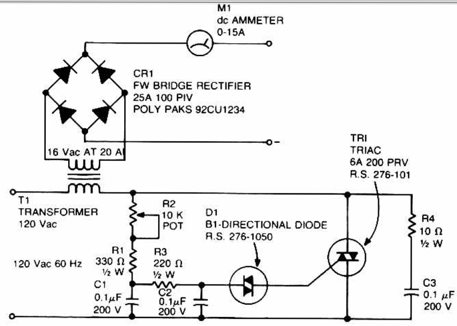
This circuit can be used to charge accumulator and cell batteries. It features a very stable output that extends the battery life and maximizes the added battery capacity. The charging process is also quite fast, optimizing the time required...
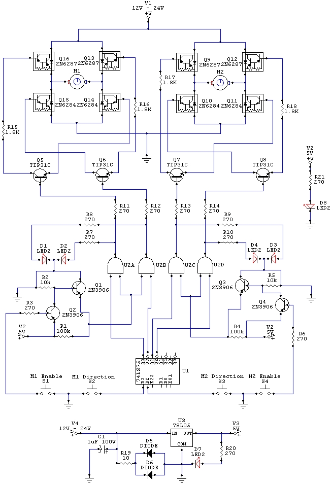
The wiring schematic played a significant role in the robot. This diagram is used to graphically display all the wiring of the motor-controlling micro-components that enabled the robot to physically move forward, backward, left, right, and stop. This diagram...
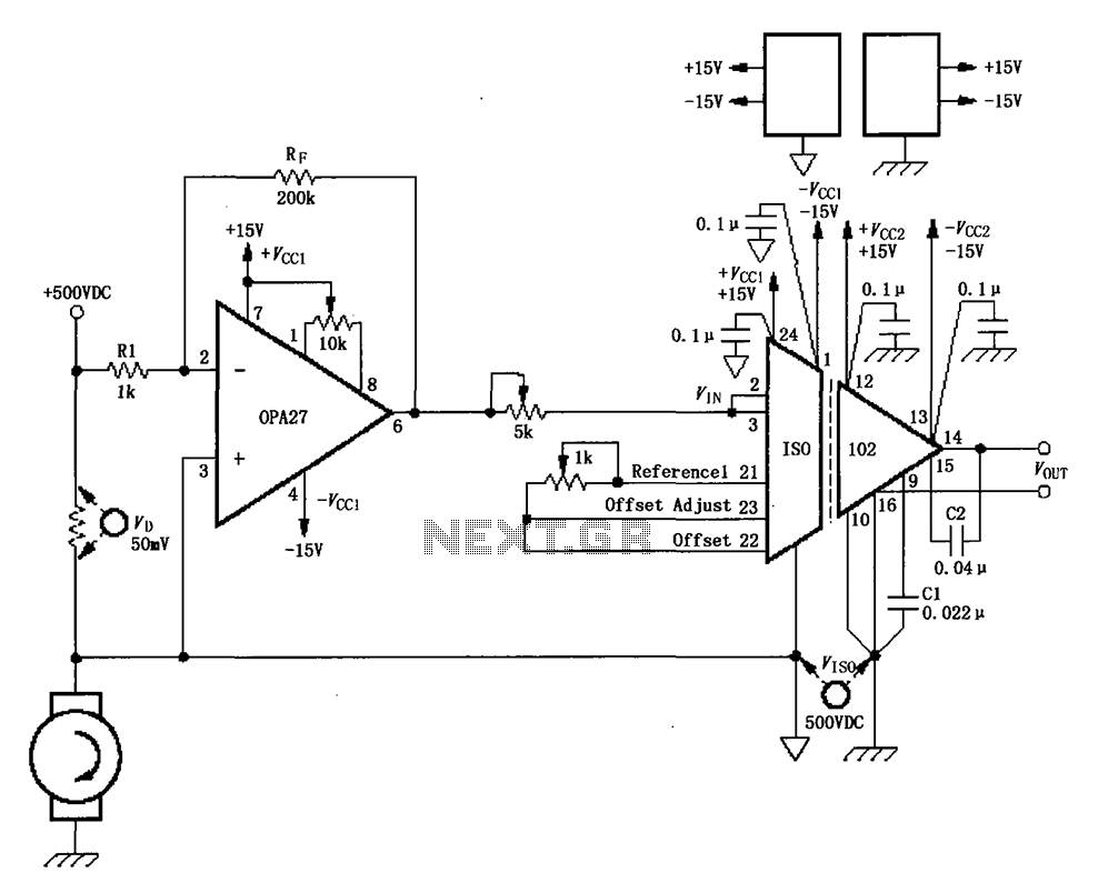
The circuit depicted in the figure consists of an ISO102 and OPA27 for measuring DC current at a voltage of +500V. It is configured between a +500V DC voltage source and a sampling resistor that is in series with...
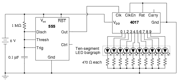
The following circuit illustrates a schematic diagram of an LED sequencer. This circuit is based on the 555 timer integrated circuit (IC). Features include a 555 timer circuit designed to debounce a mechanical switch, a 555 timer circuit to...
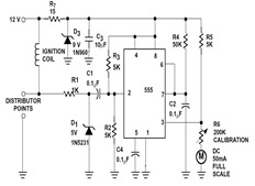
The sections available in this datasheet cover general design considerations for the 555 timer, frequently asked application questions (FAQ), design formulas, and examples of innovative applications. Examples of applications include a Missing Pulse Detector, Pulse Width Modulation (PWM), Tone...
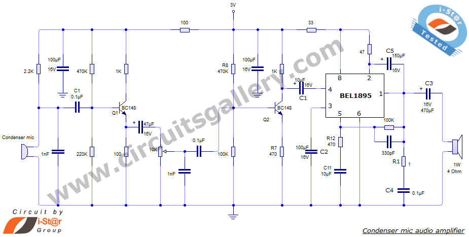
This document presents an audio amplifier circuit suitable for use in walkie-talkies, low-power transmitters, and packet radio receivers. The circuit utilizes a condenser microphone audio amplifier that delivers high-quality audio output of 0.5 watts at 3 volts. The design...