
Daylight alarm with 555

The described circuit utilizes a 555 timer IC configured in astable mode to generate a square wave output at approximately 1 kHz. This frequency is suitable for driving a speaker to produce a loud alarm sound. The light-dependent resistor (LDR) serves as a sensor that detects ambient light levels. In darkness, the resistance of the LDR is high, which keeps the base of the connected transistor in a non-conducting state. As a result, the transistor remains OFF, preventing current flow to the reset pin (pin 4) of the 555 timer, thereby keeping the timer in a reset state and stopping any oscillation.
When light is present, the resistance of the LDR decreases significantly, allowing current to flow to the base of the transistor. This action turns the transistor ON, effectively pulling the reset pin of the 555 timer high. Once the reset pin is activated, the 555 timer begins to oscillate, producing a square wave output. This output can drive a speaker, generating an audible alarm sound to wake the user.
The variable resistor, rated at 100K ohms, is crucial for adjusting the sensitivity of the circuit. By varying its resistance, the threshold light intensity required to trigger the alarm can be fine-tuned, allowing the circuit to function effectively in different lighting conditions. This adjustment capability ensures that the alarm can be set to activate only when desired, preventing false triggers from ambient light fluctuations.
Overall, this circuit is a practical application of the 555 timer and LDR technology, providing a simple yet effective solution for a light-activated alarm system.The circuit presented here wakes you up with a loud alarm at the break of the daylight. Once again the 555 timer is used here. It is working as an astable multivibrator at a frequency of about 1kHz. The circuit's operation can be explained as follows: When no light falls on the LDR, the transistor is pulled high by the variable resistor. Hence the transistor is OFF and the reset pin of the 555 is pulled low. Due the this the 555 is reset. When light falls on the LDR, its resistance decreases and pulls the base of the transistor low hence turning it ON. This pulls the reset pin 4 of the 555 high and hence enables the 555 oscillator and a sound is produced by the speaker.
The variable 100K resistor has to be adjusted to set the light intensity that triggers the alarm. 🔗 External reference
Related Circuits
This circuit gives out an alarm when its sensor is wetted by water. A 555 astable multivibrator is used here which gives a tone of about 1kHz upon detecting water. The sensor when wetted by water completes the circuit...

Pulse Generator kit will generate a frequency in KHz which can form a good test gear project. This kit is based on the classic LM555 timer IC. Input - 12 VDC Max @ 40 mA. Range - jumper selectable...

The 555 timer generates a reliable delay, enabling the driver to deactivate the alarm and eliminating the need for an external control switch that could be compromised. Additionally, the RCS prevents the activation of timer B unless it is...
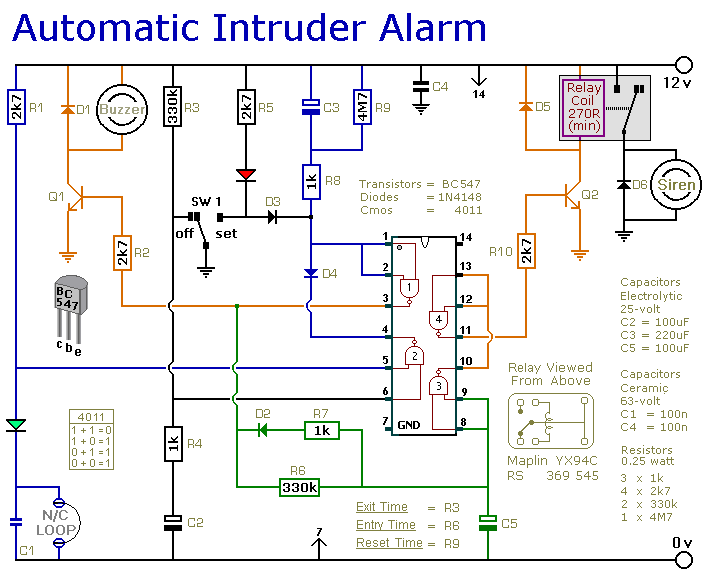
This is a simple single-zone burglar alarm circuit. Its features include automatic Exit and Entry delays and a timed Bell/Siren Cut-Off. It's easy to use. First check that the building is secure and that the green LED is lit....

The circuit operation principle of the device illustrated in the figure is as follows: When the barbed wire is intact, the output pin of the LSE is high due to the absence of contact. Consequently, the transistor VT is...

This is a simple alarm circuit using a CD4001 integrated circuit. It is designed for home, motorcycle, car, or other applications. The circuit will undergo computer simulation using Livewire, followed by printed circuit design with KiCad. SW1 is a...