
Dc linear coupler

The circuit design focuses on achieving high accuracy in analog signal transmission through optocouplers, specifically utilizing the H23 and L14H4 components. The H23 consists of an infrared emitter (IRED) and a photodetector, while the L14H4 serves as a secondary optocoupler to enhance signal fidelity. The arrangement is critical; both the H23 and L14H4 must be aligned such that the light emitted by the H23 IRED effectively illuminates the L14H4 detector. This configuration aims to achieve a collector current that matches across both detectors, thereby improving linearity in signal transmission.
In practical implementations, the circuit should allow for mechanical adjustments to the positioning of the H23 emitter to maintain the output voltage (Vqut) within the specified range of 2-8 V when the input voltage (VIN) is zero. This alignment is crucial for ensuring that the detectors operate under identical conditions, thereby minimizing discrepancies that could arise from variations in temperature or biasing conditions.
Resistance (R) plays a significant role in fine-tuning the circuit for optimal performance. While it can be adjusted to achieve a desired null level, caution is warranted, as such adjustments may lead to poorer temperature tracking. This aspect is particularly important in environments where temperature fluctuations could impact circuit performance.
The stability of the output despite variations in the power supply voltage is another key feature of this design. This characteristic allows for reliable operation in diverse conditions, making the circuit suitable for a wide range of applications, including data transmission and sensor interfacing. Testing has demonstrated that the linearity of the circuit is superior to the resolution limits of the testing equipment, indicating the effectiveness of the design in maintaining signal integrity.
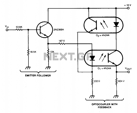
In conclusion, the described circuit exemplifies a thoughtful approach to overcoming the challenges associated with linear coupling of analog current signals using optocouplers, leveraging mechanical design and feedback control to enhance performance in practical applications.The accuracy of direct linear coupling of analog current signals via an optocoupler is determined by the coupler linearity and its temperature coefficient. Use of an additional coupler for feedback can provide linearity only if the two couplers are perfectly matched and identically biased.
These are not practical constraints in most equipment designs and indicate the need for a different design approach. One of the most successful solutions to this problem can be illustrated by using a H23 emitter-detector pair and a L14H4.
The H23 detector and L14H4 are placed so both are illuminated by the H23IRED emitter. Ideally, the circuit is mechanically designed such that the H23 emitter may be positioned to provide Vqut = 2-8 V when VIN = 0, thereby insuring collector current matching in the detectors. Then all three devices are locked in position relative to each other. Otherwise, R may be adjusted to provide the proper null level, although temperature tracking should prove worse when R is adjusted.
Note that the input bias is dependent on power supply voltage, although the output is relatively independent of supply variations. Testing indicated linearity was better than could be resolved, due to alignment motion caused by using plastic tape to lock positions.
The concept of feedback control of IRED power output is useful for both information transmission and sensing circuitry.
Related Circuits
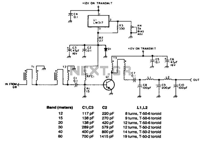
This linear amplifier provides a 10-W PEP output with a 1.25-W drive on the 10 m band. The transformers, T1, T2, and T3, consist of 10 turns of bifilar windings on an FT-50-43 toroidal core and are designed for...
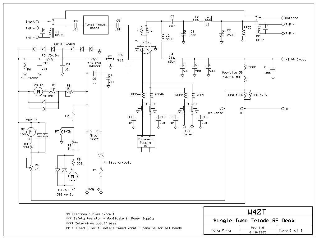
Tube Tester and Filament Burn-In Jig - This device is designed for prolonged heating of tubes before testing them for insertion into an amplifier. It is crucial to note that the filament generates significant heat, which can raise the...
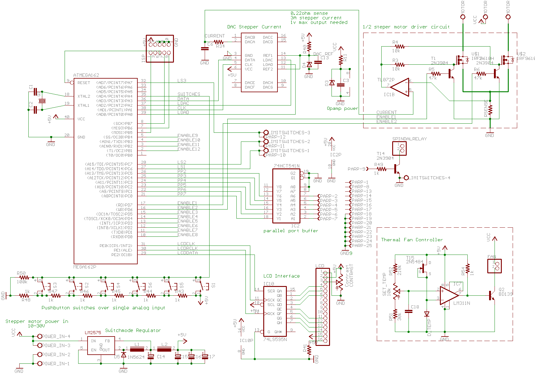
A basic CNC machine was built for a university project, and the completed machine will undergo upgrades over the coming months. The plan includes replacing the small 48-step stepper motors with larger 200-step motors to enhance performance. The project involves...
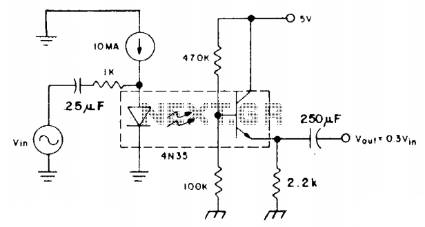
The coupler is biased in the linear region using a 10 mA DC bias on the infrared emitting diode (IRED) and a voltage divider connected to the base of the phototransistor. This configuration allows the photodiode current to flow...
A circuit stabilizes the current-transfer ratio (CTR) of an optically coupled isolator used as a linear transducer. The optocoupler produces a voltage output that is proportional to, but electrically isolated from, the voltage input. However, the output voltage is...
This is the circuit of a 500 watt linear amplifier, based upon a design by Frits Geerligs, PA0FRI. The circuit uses four PL519 TV line output valves in a very simple circuit that will deliver over 450 watts at...