
Stable optocoupler

The circuit described is designed to maintain a stable current-transfer ratio (CTR) in an optically coupled isolator, commonly referred to as an optocoupler, which serves as a linear transducer. The primary function of the optocoupler is to provide electrical isolation between its input and output while producing a voltage output that is proportional to the input voltage. This characteristic is essential in applications where signal integrity and safety are paramount.
The performance of the optocoupler can be adversely affected by variations in the CTR, which can fluctuate due to changes in temperature, input current, and aging of the device. These variations can lead to inaccuracies in the output voltage, making it crucial to implement a stabilization mechanism. The circuit achieves this by integrating a feedback loop that utilizes a second optocoupler.
In this configuration, the feedback circuit continuously monitors the output voltage and generates a feedback signal that counteracts any deviations in the CTR. This opposing signal serves to adjust the input to the primary optocoupler, effectively compensating for any changes in the CTR. As a result, the overall stability of the output voltage is enhanced, ensuring that it remains consistent even in the face of environmental changes or component aging.
The design of the feedback circuit is critical, as it must be responsive enough to detect changes in the output voltage quickly while also being robust against noise and other disturbances. The inclusion of the second optocoupler in the feedback loop not only aids in stabilizing the CTR but also maintains the electrical isolation between the control and output sections of the circuit.
Overall, this circuit design is particularly beneficial in applications requiring precise voltage measurement and control, such as in instrumentation and industrial automation systems, where reliability and accuracy are essential.A circuit stabilizes the current-transfer ratio (CTR) of an optically coupled isolator used as a linear transducer. The optocoupler produces a voltage output that is proportional to—but electrically isolated from—the voltage input.
However, the output voltage is directly affected by changes in the CTR, and the CTR can change substantially with temperature and current. To a lesser extent the CTR changes with time over the life of the optocoupler. The circuit employs a feedback circuit containing a second optocoupler. The feedback signal tends to oppose changes in the overall CTR.
Related Circuits
The 555 timer is named for its primary operation mode, which is monostable. In this mode, it does not strictly conform to the definition of an oscillator, as it requires an input signal to trigger its operation. However, the...
Powering this circuit with a 6V alkaline battery operates effectively with 100µF capacitors. However, there is an issue when attempting to replace the LED with a DPDT relay; a 6V relay previously available does not activate. Additionally, when using...
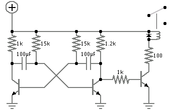
The astable multivibrator presented in Wikipedia and college materials is depicted on the left side of the image. In contrast, the schematic on the right side is sourced from an LTSpice example. The right schematic is incorrectly drawn, and...
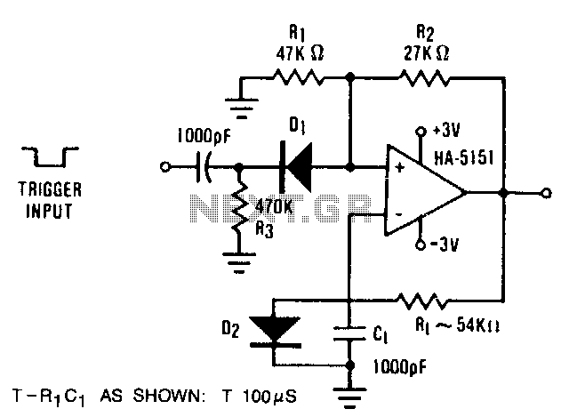
The circuit demonstrates the functionality of the HA-5151 as a battery-powered monostable multivibrator. In this configuration, the time constant is set to 0.632, simplifying the time constant equation to T = R1 * C1. Diode D2 is employed to...
This regulated power supply is adjustable between a few volts and 15V using P1, while P2 is used to set the upper limit at 15.0V. The value of R6 is calculated as 0.7V divided by Imax, where Imax represents...
A small circuit designed for various time measurement applications. It features an audible sound signal from the buzzer BZ1 and has the capability to drive an external circuit through the optocoupler IC2, once the appropriate circuit is connected to...