
DC Motor Control
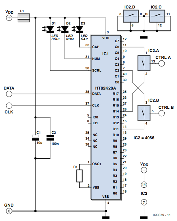
The DC motor control circuit is designed to provide precise control over the operation of a DC motor, enabling various functionalities such as forward rotation, reverse rotation, gradual slowing, and complete stopping. The circuit typically comprises a microcontroller unit (MCU) that interfaces with the motor driver, which is responsible for supplying the appropriate voltage and current to the motor based on the control signals received from the MCU.
The MCU can be programmed to execute specific control algorithms that determine the motor's behavior in response to user inputs or sensor feedback. For instance, pulse-width modulation (PWM) can be employed to regulate the speed of the motor by varying the duty cycle of the signals sent to the motor driver. This allows for smooth acceleration and deceleration, enhancing the overall performance of the motor control system.
The circuit may include additional components such as limit switches or encoders to provide feedback on the motor's position or speed, enabling closed-loop control. This feedback can be processed by the MCU to make real-time adjustments to the motor's operation, ensuring accurate positioning and speed control.
Power supply considerations are also crucial in the design of the circuit. The voltage and current ratings of the motor should be matched with the specifications of the motor driver and the power supply to prevent damage and ensure reliable operation.
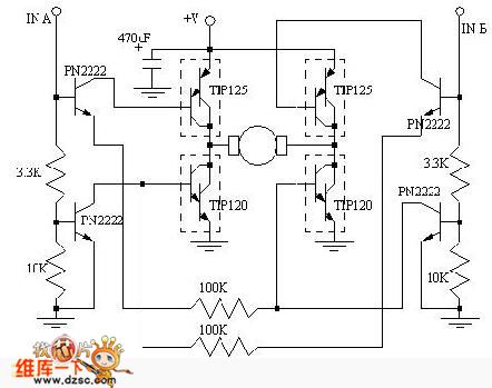
In summary, this DC motor control circuit serves as a versatile solution for various applications requiring precise motor control, enabling functionalities such as co-rotation, rollback, slowing, and stopping, all managed efficiently by an MCU.Aboutthe DC motor control problem, This circuit is hoped to help those people who have the actual needs. This circuit`s corotation, rollback, slowing and stopping functions can be controlled by the connected MCU..
🔗 External reference
Related Circuits
This circuit utilizes small switching transistors, with a maximum motor drive current limited to approximately 250 mA at 5V. Testing has been conducted across a voltage range from 3V to 21V, and with certain component modifications, it may be...
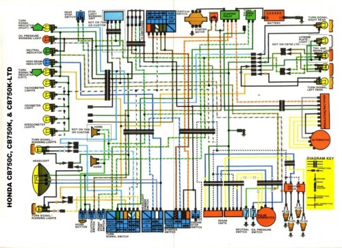
Many inquiries arise regarding motorcycle wiring, particularly among individuals attempting to repair their blinkers or seeking to streamline electronics for custom builds. A crucial aspect of constructing any chopper, bobber, cafe racer, brat bike, or rat rod involves eliminating...
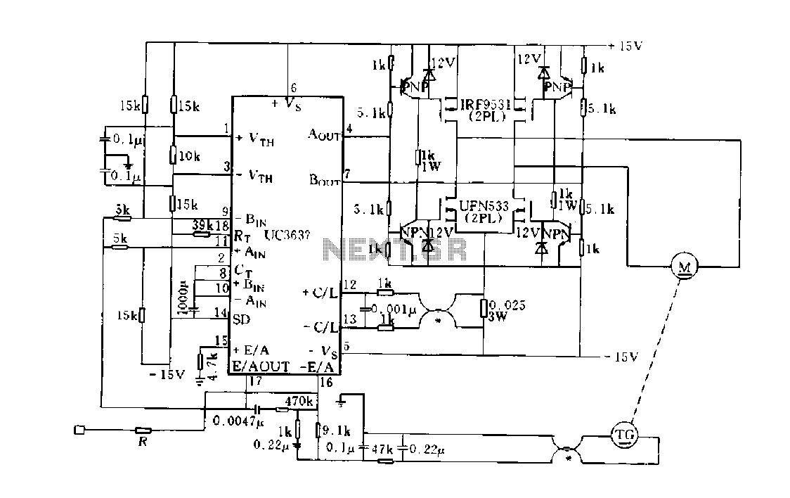
DC motor-generator speed closed-loop control utilizing the UC3637 internal error differential amplifier (EA). After the tachometer generates a speed voltage signal, it is filtered with the speed command electrical voltage comparator. Following error correction, the signal is amplified to...
One of the more challenging aspects of creating a control or security system that utilizes a PC, such as a burglar alarm, is connecting the sensors to the computer. This typically requires specialized interface expansion boards, and programming that...
The following circuit illustrates a stepper motor controller. This circuit is based on the PIC16F84A integrated circuit. Features: a transistor is utilized to drive the motor. The stepper motor controller circuit employs the PIC16F84A microcontroller, which serves as the central...
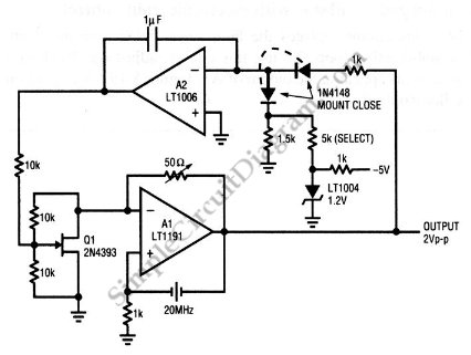
This is a quartz-stabilized oscillator circuit with electronic gain control. Replacing the common filament lamp for amplitude stabilization, this circuit uses... This circuit represents a quartz-stabilized oscillator featuring electronic gain control, which enhances the stability and precision of the output...