
DC Motor Control circuit
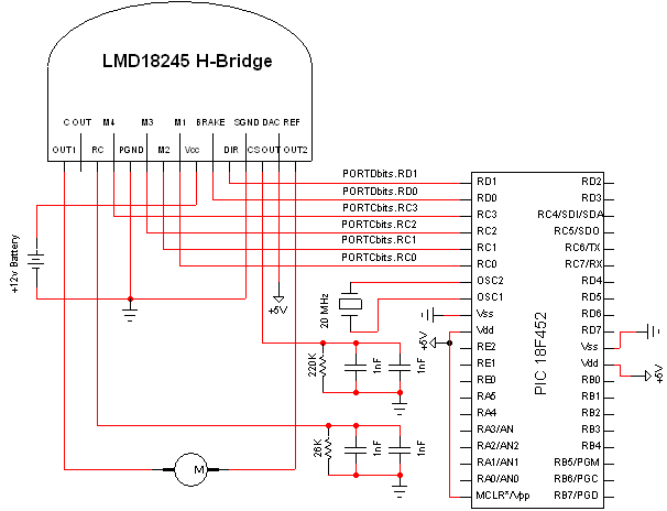
The schematic design integrates various electronic components to facilitate the intended functionality. The core of the circuit is based on a PIC microcontroller, which serves as the central processing unit. The connections to the microcontroller are critical, as they determine how the device interacts with other components in the circuit.
The use of a 220k resistor is specified, which plays a crucial role in setting the appropriate current levels within the circuit. If a 220k resistor is not available, selecting a higher resistance value is advisable to ensure that the circuit operates within safe parameters. This approach will help prevent excessive current flow that could potentially damage sensitive components.
The circuit layout is designed to be compatible with the Olimex P-40 Development board, which provides a convenient platform for prototyping and testing. The development board typically includes additional features such as power supply regulation and I/O pin access, making it easier to implement the schematic without needing extensive modifications.
It is essential to ensure that the software programmed into the PIC microcontroller aligns with the intended operation of the circuit. The preprogrammed software must be loaded onto the microcontroller before testing the schematic to confirm that it functions as expected.
In summary, the schematic effectively demonstrates the integration of essential electronic components, emphasizing the importance of precise resistor values and the compatibility with development boards for successful implementation. Proper attention to these details will facilitate a successful experiment and ensure reliable functionality.The schematic seen below uses all the hardware components we`ve seen up to this point. If you`re following along with this tutorial be sure to follow it exactly as seen below. If you don`t have 220k resistor use the closest value you can find near it, preferrably higher. Components are labeled to the best of my ability. Parts hooked up to the PIC are minial and it should be recognized that this experiment actually uses the Olimex P-40 Development board and not a bare bones PIC layout as seen in the schematic. However if you choose to follow the schematic exactly it will work the same as it would with the development board, provided of course that the software is preprogrammed onto the PIC.
🔗 External reference
Related Circuits
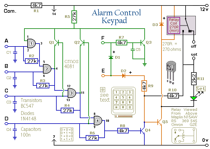
Pressing a single key on the keypad energizes the relay. Entering a four-digit code of your choice de-energizes the relay. The circuit was designed to control the Modular Burglar Alarm System but can have other applications. A five-digit version...
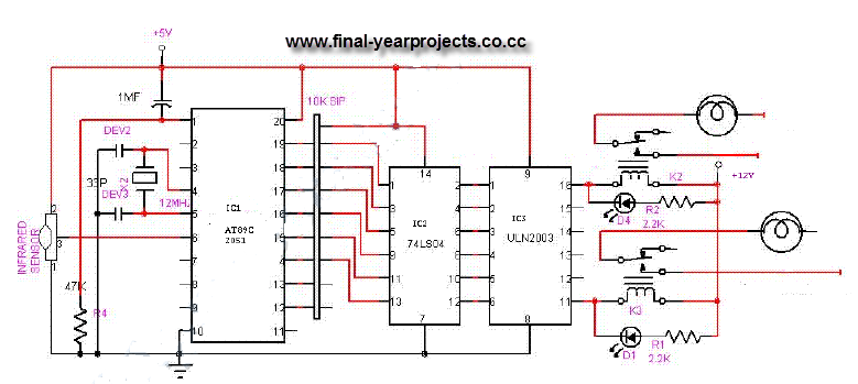
This is a comprehensive electrical project report on an Infrared Remote Control On/Off Switch, submitted to fulfill the requirements for the Bachelor of Engineering degree in Electrical Engineering. The project is designed to control the operation of home appliances...
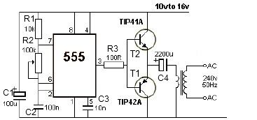
12V power inverter circuit utilizing a 555 timer for an electronic project. The 12V power inverter circuit is designed to convert a DC voltage of 12 volts into an AC voltage suitable for powering small electronic devices. The core component...
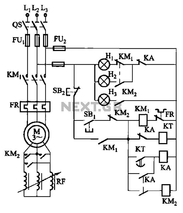
The circuit depicted in Figure 3-165 utilizes a time relay (KT) for controlling the start-up time. Indicator light Hi serves as the power indicator, H2 is designated for the start lights, and H3 functions as the running lights. The circuit...
This sensitive touch potentiometer utilizes IC1 (CA3130), an operational amplifier known for its high input impedance. When a finger touches the Se1 sensor, C2... This circuit design incorporates a touch-sensitive potentiometer that leverages the CA3130 operational amplifier to achieve high...
This circuit resembles an LED clock but utilizes 12 neon indicator lamps in place of LEDs. It operates on two high-capacity nickel-cadmium cells (2.5 volts), providing power for several weeks. A small switching power supply generates the high voltage...