
Model Train Throttle Control
The circuit described operates with a momentum feature that simulates realistic train behavior by controlling the acceleration and deceleration profiles. The system is capable of handling a maximum load of 1 A at 15 V, making it suitable for small model train applications.
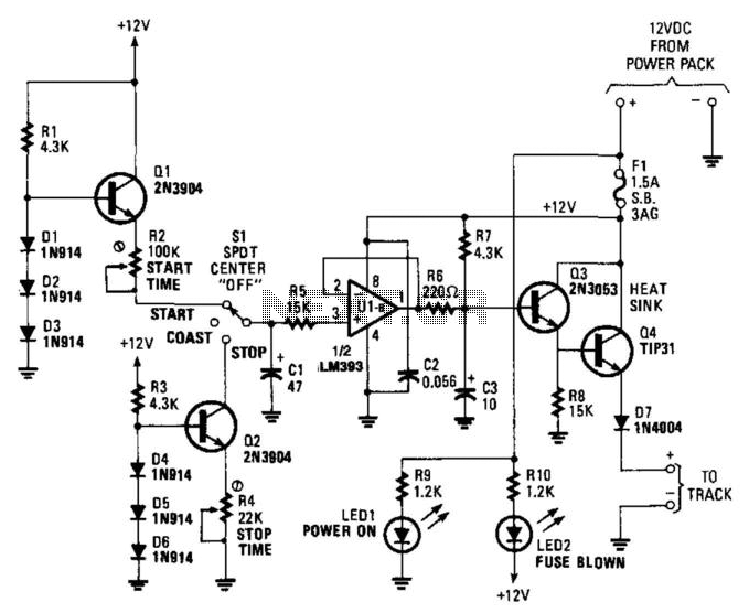
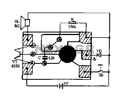
In the start mode, the operation begins with current source Q1, which charges capacitor C1. The resistor R2 plays a crucial role in determining the rate at which C1 charges, thereby influencing the startup time. This allows for customization of the acceleration curve to enhance the realism of the train's movement.
Once the train reaches the desired speed, the stop mode is activated. Current sink Q2 takes over to discharge capacitor C1, with resistor R4 setting the rate of discharge. This configuration allows for a gradual decrease in speed, simulating the natural deceleration of a train.
During the coast mode, operational amplifier U1 is employed to maintain a near-constant output from capacitor C1. The low current draw from U1 ensures that the train does not come to an immediate stop but rather coasts for a while, contributing to the overall realistic behavior of the system.
Transistors Q3 and Q4 are configured as a Darlington pair, which provides high current gain and effectively amplifies the output signal from U1. This amplification is critical for driving the load, ensuring that the train operates smoothly without any sudden interruptions in power.
Diode D7 serves to slightly reduce the output voltage, providing a necessary adjustment to the circuit's performance. The option to add another diode in series allows for further control over the output voltage, enabling the system to reach a complete stop when required.
Overall, this circuit design effectively integrates various components to create a control system that mimics the realistic operation of model trains, enhancing the user experience through its momentum feature and adjustable parameters. What makes this control unique is its momentum feature, which adds a degree of realism. The circuit will opera te well for trains that draw up to 1 A at 15 V. None of the components are critical. In the start mode, current source Ql charges capacitor CI. The charge current and start-up time are adjusted by resistor R2. In the stop mode, current-sink Q2 discharges capacitor CI. The discharge current and stop time are set by resistor R4. In the coast mode, op amp Ul draws very little current from CI, so the speed will remain nearly constant for some time, and then gradually decrease. Transistors Q3 and Q4 form a Darlington emitter-follower to amplify the output of Ul. Diode D7 reduces the output by about 0.8 V. Another diode could be added in series to decrease the output to 0 in the stop mode. 🔗 External reference
Related Circuits
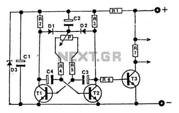
This circuit is designed for controlling motors, lamps, heating elements, and similar devices continuously from nearly zero to maximum capacity (5-95%). It utilizes impulse control for nearly lossless operation, providing almost total torque for motors. The transistor T3 must...
The simplest of all motor controllers (besides a straight on/off switch) is the contactor controller. I designed this contactor controller for use in my electric scooter project. It is based around three 12V relays, two 12V batteries, two switches...
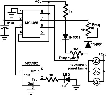
This circuit utilizes an MC3392 low-side protected switch along with an MC1455 timing circuit to create a dimmer control for automotive instrumentation panel lamps. The brightness of incandescent lamps can be adjusted by applying Pulse Width Modulation (PWM) to...
The circuit consists of an infrared transmitter-receiver pair that uses infrared beam transmission to switch the toy car on or off. It can be modified to allow the toy car to turn left or right. To operate the toy...
The remote control transmits encoded signals. Each time a key is pressed, the relevant code is transmitted, usually repeating it many times to ensure reception. This encoded signals travels over a radio or infrared-light beam, to eventually get captured...
Constantly changing light and sound analog controller circuit 02 The circuit described is an analog controller designed to modulate light and sound in a dynamic manner. It typically utilizes components such as operational amplifiers, resistors, capacitors, and transistors to achieve...
Warning: include(partials/cookie-banner.php): Failed to open stream: Permission denied in /var/www/html/nextgr/view-circuit.php on line 713
Warning: include(): Failed opening 'partials/cookie-banner.php' for inclusion (include_path='.:/usr/share/php') in /var/www/html/nextgr/view-circuit.php on line 713