
Dc Motor-Speed Control
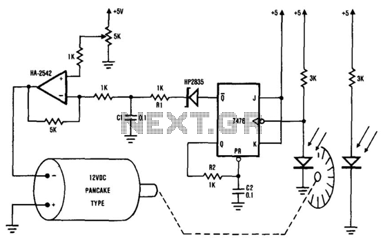
The described system utilizes the HA-2542 operational amplifier as a key component for speed regulation of a 12 V DC motor. The position encoder plays a crucial role by generating constant-width pulses that are integrated to create a reference voltage. This voltage is indicative of the motor's current speed and is essential for feedback control.
The operational amplifier functions in a closed-loop configuration, where the inverting input receives the reference voltage derived from the encoder pulses. The non-inverting input is set to a predetermined voltage that corresponds to the target speed of the motor. The operational amplifier compares these two voltages, and any discrepancy between them is processed to produce an output signal that adjusts the motor's drive voltage.
This feedback mechanism ensures that the motor operates at the desired speed by continuously monitoring its actual speed and making real-time adjustments. The capacitor C1 plays a vital role in smoothing out the pulse signal from the encoder, allowing for a more stable reference voltage. This design is particularly effective in applications requiring precise speed control, such as robotics, conveyor systems, and automated machinery.
The overall system architecture illustrates the integration of electronic components to achieve efficient motor control, highlighting the importance of feedback loops in maintaining desired operational parameters. The system shown consists of the HA-2542, a small 12-Vdc motor, and a position encoder. During operation, the encode r causes a series of "constant-width" pulses to charge CI. The integrated pulses develop a reference voltage, which is proportional to motor speed and is applied to the inverting input of HA-2542. The noninverting input is held at a constant voltage, which represents the desired motor speed. A difference between these two inputs will send a corrected drive signal to the motor, which completes the speed control system loop.
🔗 External reference
Related Circuits
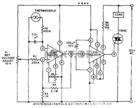
This control, featuring zero-voltage load switching, utilizes a CA3130 BiMOS operational amplifier and a CA3079 zero-voltage switch. The CA3130, functioning as a comparator, is particularly suited for comparing the low voltages produced by a thermocouple against an adjustable reference...
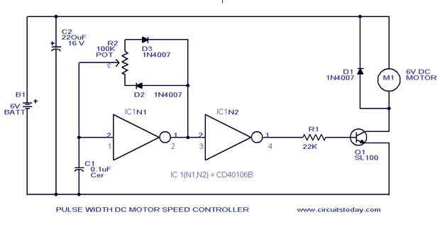
A simple PWM motor speed control circuit with a diagram and schematic for low power DC motors. This easy-to-make PWM DC motor controller is created using the IC CD40106B. The PWM (Pulse Width Modulation) motor speed control circuit utilizes the...
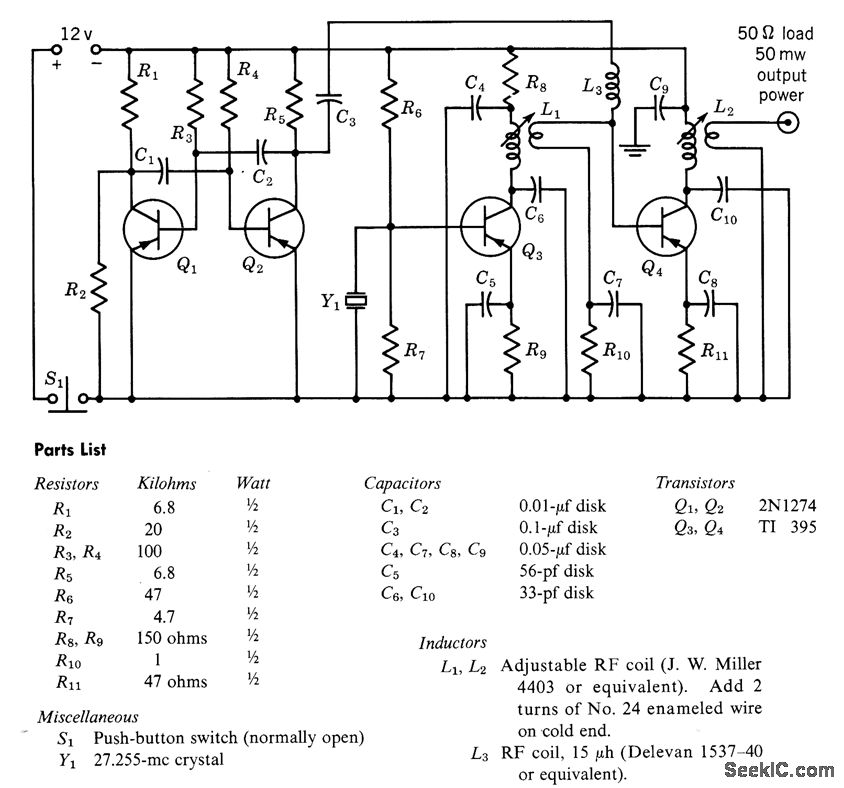
A free-running multivibrator activates power amplifier Q4 for audio applications. The operational range is approximately 1 mile, and capacitor C6 is used to tune the collector of the oscillator to the crystal frequency. - Texas Instruments Inc., "Transistor Circuit...
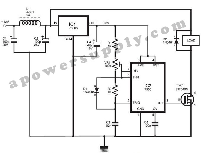
This DC power supply controller is regulated by pulse width modulation (PWM), which is generated by a circuit utilizing timer IC2 7555 according to a specific duty cycle formula. The described DC power supply controller employs a timer IC, specifically...
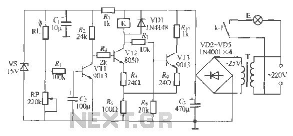
The circuit operates as a light-activated switch that controls white moving lights. It features high sensitivity, stable performance, and good anti-interference characteristics. A photosensitive resistor (RI) is employed to detect ambient light levels. During the day, the resistor exhibits...
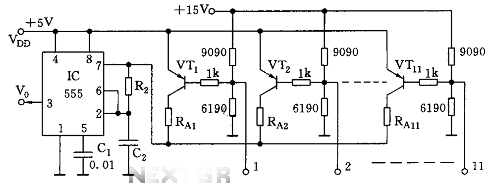
As illustrated in the figure, the base bias circuit for transistors VT1 to VT11 is designed to accept binary data, where a high level represents 1 and a low level represents 0. This configuration allows for 2048 combinations of...