
PWM Motor Speed Control Circuit with Diagram for DC Motor
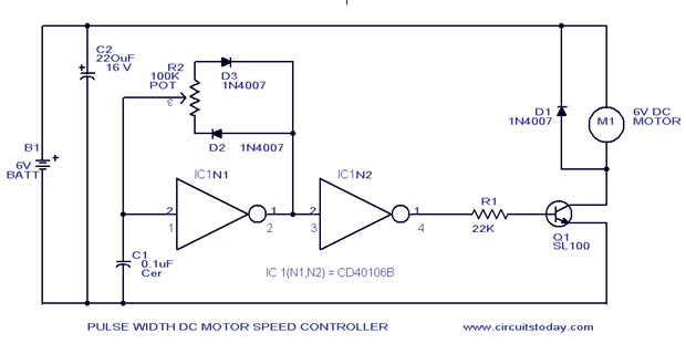
The PWM (Pulse Width Modulation) motor speed control circuit utilizes the CD40106B integrated circuit, which is a Schmitt trigger inverter. This design is particularly suitable for controlling the speed of low-power DC motors by varying the duty cycle of the PWM signal delivered to the motor.
The circuit typically consists of the CD40106B, resistors, capacitors, and the DC motor. The Schmitt trigger inverter provides a stable output that can drive the MOSFET or transistor used to control the motor. The frequency of the PWM signal is determined by the values of the resistors and capacitors connected to the input of the inverter.
When the circuit is powered, the capacitor charges and discharges through the resistors, generating a square wave output. By adjusting the resistance or capacitance, the duty cycle of the PWM signal can be altered, which effectively changes the average voltage supplied to the motor. This results in variable speed control, allowing for precise adjustments to the motor's operation.
The schematic diagram typically shows the connections between the CD40106B, the power supply, the motor, and the control components. It is essential to ensure that the components are rated appropriately for the voltage and current requirements of the motor to prevent damage. Additionally, the circuit can be enhanced with features such as an on/off switch or feedback mechanisms for more advanced control.
This PWM motor controller is an efficient and straightforward solution for applications requiring speed regulation of low-power DC motors, making it suitable for hobby projects and small-scale automation systems.A simple PWM motor speed control circuit with diagram and schematic for low power dc motors. This easy to make pwm dc motor controller is made using IC CD40106B.. 🔗 External reference
Related Circuits
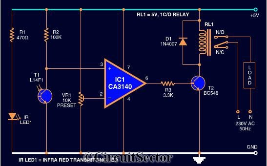
The circuit diagram presented is a highly sensitive wireless relay switch designed to control home appliances such as flush systems and hand dryers. This wireless switch operates without the need for a remote control. It functions by simply moving...
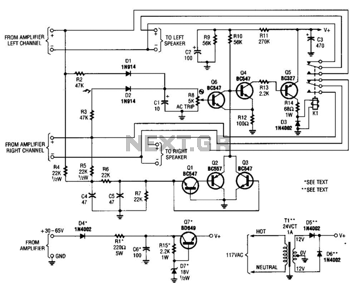
Most of the transistors in this speaker protector operate as switches. Normally, Q4, Q5, and K1 are activated, allowing the speakers to connect to the amplifier. However, if a significant DC voltage is detected at the amplifier output, either...
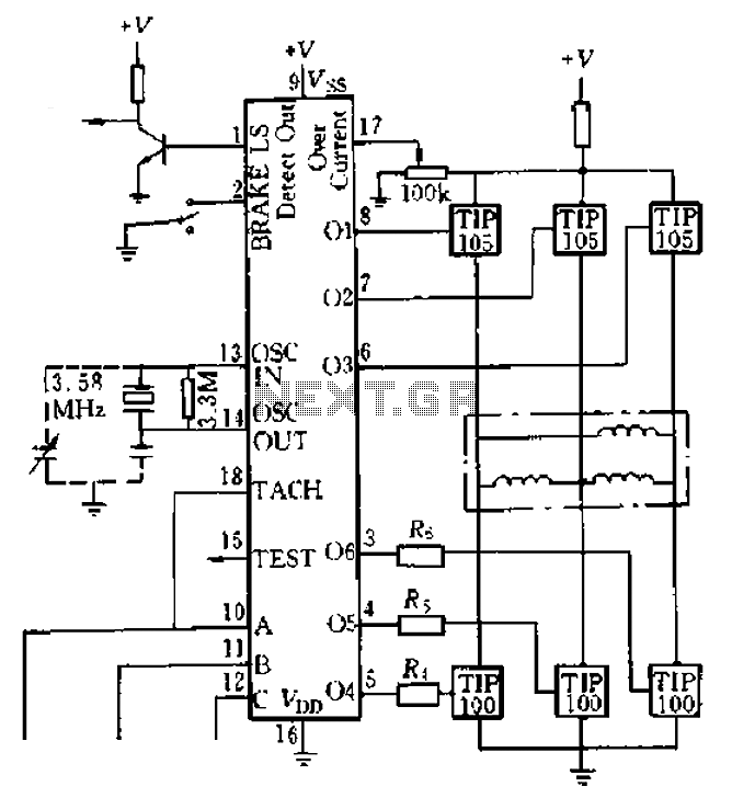
Four application examples are presented in the figure, focusing on a three-phase brushless DC motor used in Winchester disk drives with an operating speed of 3600 RPM. Although the original design specifies an operating speed of 3600 RPM, alternative...
This FET audio mixer demonstrates the versatility of FETs. Originally designed for high-frequency applications, FETs can also effectively handle audio frequencies, showcasing exceptional performance in this domain. The circuit can accommodate an unlimited number of inputs, provided that the...
This circuit is designed to indicate when a plant requires watering. An LED blinks at a low frequency when the soil in the flower pot is excessively dry, turning off as the moisture level rises. The sensitivity of the...
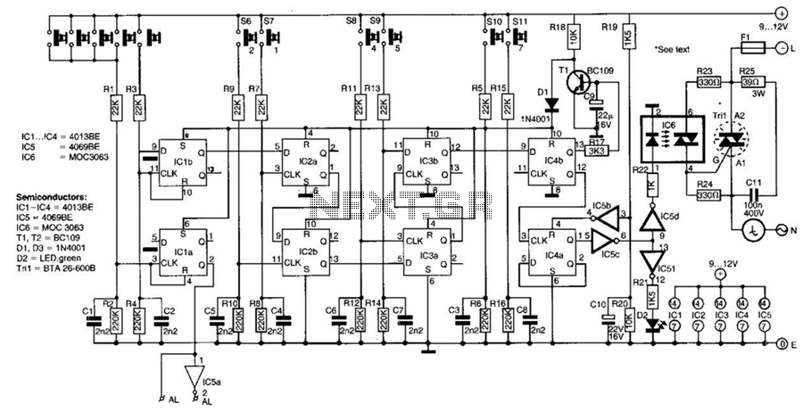
This switch utilizes four CD4013BE dual flip-flops, an inverter, and an optoisolator to control a triac, allowing it to switch a 25-A AC load current. A standard 4x3 telephone keypad is employed for entering a 6-digit code. In the...