
APPLIANCE CONTROL USING TIMER - PROJECT
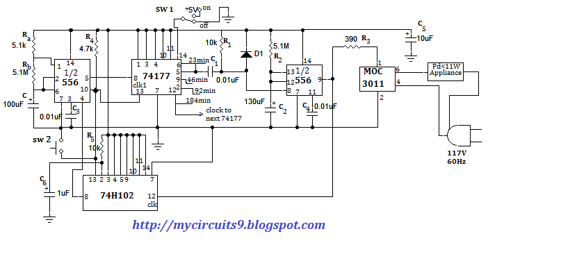
The electronic circuit for device control using a timer encompasses several key components and functional blocks. At its core, the square wave generator produces a continuous square wave signal that serves as the timing reference for the entire system. This generator can be implemented using a 555 timer IC configured in astable mode, generating a square wave of desired frequency and duty cycle.
The divide by N counters, such as the 7490 and 74192, play a crucial role in determining the timing intervals for appliance activation. These counters can be configured to achieve specific division factors, allowing for precise control over when the appliance is turned on and off. For instance, cascading multiple 7490 counters can create longer time delays by effectively multiplying the division factor.
The one-shot multivibrator, often realized using another 555 timer in monostable mode, is essential for producing a single output pulse of a defined width. The output pulse width is determined by the RC time constant, which can be adjusted based on the desired operational duration of the appliance. The output of the one-shot directly controls the optical coupler, which acts as an interface between the low-power control circuit and the high-power appliance.
The optical coupler, also known as an opto-isolator, ensures that the control circuit remains electrically isolated from the appliance, enhancing safety and preventing potential damage to sensitive components. The activation of the optical coupler allows current to flow to the appliance, turning it on, while its deactivation cuts off the current, turning the appliance off.
The reset control circuit is critical for maintaining the operational integrity of the system. It ensures that the square wave generator can be halted and reset after each cycle, allowing the system to prepare for the next timing event. This circuit typically includes a simple transistor or relay configuration that responds to the negative transition of the one-shot's output pulse.
Overall, this electronic project demonstrates a practical application of digital electronics and control systems, providing a versatile solution for automated appliance management in residential and commercial settings.I am going to present you fabulous Electronic project, DEVICE CONTROL USING TIMER. By using this circuit you can turn ON an appliance at a desired time for a specific time interval. You can use this concept to control the operation of a furnace or central air conditioning unit so that it comes on at a desired time. For example, a timer may be used to shut off the furnace in the house after 10 P. M turn it back ON at 5 A. M. This arrangement will help to save energy and money. The concepts of appliance timers can also be used in switching house lights on and off at regular intervals, especially the owner is on vacation. This provision should discourage burglars. In fact, when cyclic operation of the timer is desired, the reset control circuit is not needed. As shown in block diagram, the output of the square wave generator is used as a clock (trigger signal) for the divide by N counters.
A divide by N counter is a digital IC that produces a single output pulse for every N input pulses, where N is an integer. The integer N is commonly called the modulus of the counter. There are basically two types of divide by N counters fixed and programmable. For example, the 7490 is the fixed modulus type and can be used as a divide by 5 or divide by 10 counter.
On the other hand, the 74192 is a programmable counter that can be programmed to divide from 1t0 15. Often to increase the resultant output count, the fixed modulus type counters are connected in series(cascaded). In this arrangement the output of the first counter is the input to the second, output of second is the input to the third and so on using the cascading technique, time delays of hours, days or even weeks can be achieved.
The output of the divide by N counters is then applied to a one-shot (monostable) multivibrator, the output of which in turn drives the optical coupler. The output pulse width of the one-shot controls the time an optical coupler is on. The output of the monostable multivibrator is also applied to the reset control circuit, which halts the square wave generator and also resets the circuit for restart operation.
The resistor capacitor combination used for the monostable determines its output pulse width. When the output pulse goes high, the optical coupler is triggered and the appliance turns on. On the other hand, when the output pulse width of the monostable goes low, the optical coupler is disabled and the appliance turns off. At the same time, the negative transition of the pulse also triggers the reset control circuit, which in turn shuts off the square wave generator.
Thus the circuit is ready for the next cycle. 🔗 External reference
Related Circuits

Usually we see Digital clock on LCD or 7 segment. But, this AVR Digital Clock which is designed by Ficara Emilio displayed on Oscilloscope. The project uses ATtiny 2313 as the main controller. What an interesting microcontroller project. Source...
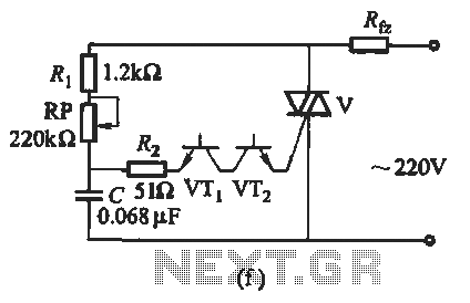
The introduction for a unidirectional thyristor trigger circuit is also applicable to the TRIAC. Various configurations are presented in Figure 16-28. Figures 16-28 (a) and (b) illustrate a direct trigger circuit; Figure 16-28 (c) depicts a dual diode trigger...
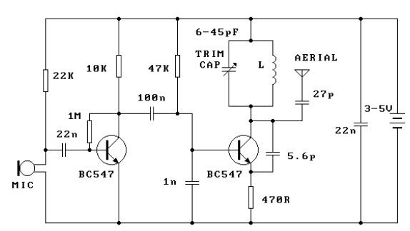
This FM transmitter circuit is very simple and has an acceptable transmission range. The signal transmitted from this FM transmitter circuit can be received at almost 300 meters in open air. The circuit requires a 3-volt operating voltage and...
The first servo controller project at http://www.rentron.com/servo.htm had the com port fixed at com1. This new version will seek out the available com ports on your PC and then let you select the desired port and baud rates. It...
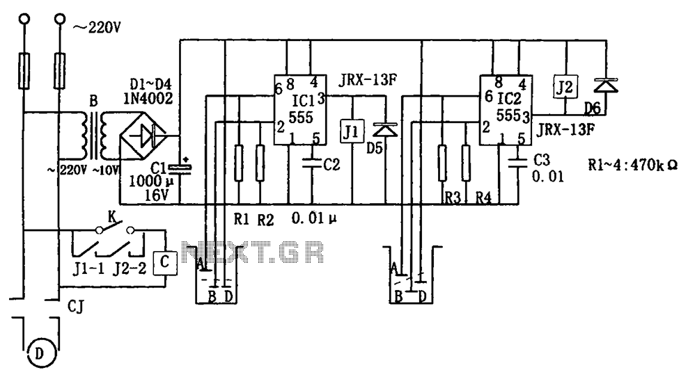
The level control circuit comprises a step-down rectifier circuit, a trigger circuit utilizing two 555 timer ICs (IC1 and IC2), and a relay control circuit. The rectifier circuit is responsible for providing the necessary DC voltage for the flip-flop...
This circuit demonstrates that microprocessors, PCs, and modern ultra-accurate Digital-to-Analog Converters (DACs) are excessive for controlling four relays in sequence based on a control voltage ranging from 2.4 V to 12 V. By utilizing equal resistors in a ladder...