
Infrared control dimming circuit
The infrared remote control dimmer circuit is designed to provide a convenient and efficient means of controlling the brightness of lamps wirelessly. The KA2184 integrated circuit plays a crucial role in processing the infrared signals received from the remote control. Upon receiving a signal, the KA2184 activates the transistor VT, which in turn controls the TRIAC that regulates the power delivered to the lamp. This allows for smooth transitions in brightness, enhancing user experience.
The LS7232 serves as the core of the dimming functionality, acting as an auxiliary input that interprets the high-level signals from the dimming circuit. The use of a PMOS IC necessitates careful consideration of power connections to ensure proper operation, as its polarity requirements differ from typical CMOS components. This design choice enhances the reliability and performance of the circuit.
In terms of power supply, the circuit employs a half-wave rectification method, which is efficient for low-power applications such as lamp dimming. The addition of the inductor alongside the buck capacitor significantly reduces voltage spikes and noise, which is essential for maintaining stable operation and protecting sensitive components from potential damage.
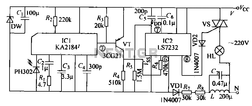
Overall, this infrared remote control dimmer circuit exemplifies a practical application of modern electronic components to achieve user-friendly lighting control, showcasing the integration of various technologies to enhance everyday functionality.Receiving circuit as shown, when the infrared receiver receives the remote control signal emitted by the transmitter, after KA2184 processed by the pin output low. This added directly to the VT low base, it is turned on, its collector current output at the upper end of the formation of a high-level output R4 out. This high level is applied to the LS7232 by R6 dimming circuit auxiliary input ( feet). As the dimming control signal. This is an infrared remote control dimmer circuit, when it pin input trigger signal, it will continuously pin output control bidirectional thyristor control pulses through the foot, so that the TRIAC conduction angle at 410-160.
Changes between. With bi-product of the thyristor conduction angle changes, but also by the lights from the dark to light or light to dark, thus realizing the lamp dimming control. In the dimming process when required by the dark to bright lights, press and hold the button on the remote control transmitter continuously transmits a control signal.
Then you can see when the lights gradually brighten t When you reach the desired brightness immediately release the PTT button, then the brightness of the lamp will stay in this position. If continuous press down, the fork will gradually darken lights from light until extinguished. Note: LS7232 is a PMOS type IC, so its power polarity with conventional CMOS circuits contrary, that it's n.
It should be connected to the negative power supply terminal, and the Vss terminal should be connected to the positive supply. The circuit power is still using AC power supply, capacitor C7 buck, half-wave rectifier diode VDI. And other different capacitor step-down power supply circuit is that the power of the buck capacitor C7 in parallel with a 220yH inductance, its role is to absorb I.
S7232 harmonics generated to prevent it interfering with other electrical appliances through the power cord.
Related Circuits
A few designs for remote control switches, using VG40T and VG40R remote control pair, are shown here. The miniature transmitter module shown in Fig. 1, which just measures 34 mm x 29 mm x 10 mm, can be used...
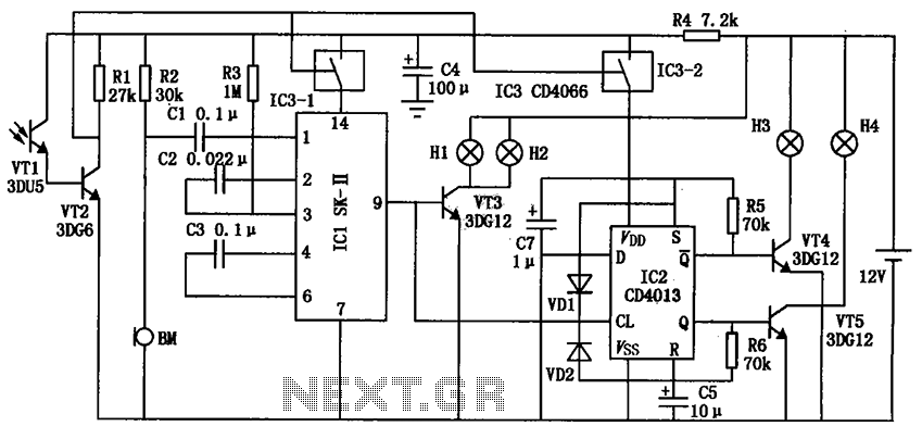
The automatic electronic circuit depicted in the figure consists primarily of a voice circuit, an oscillation circuit, and a driving section for the display circuit. The automatic electronic circuit integrates several essential components to achieve its functionality. The voice circuit...
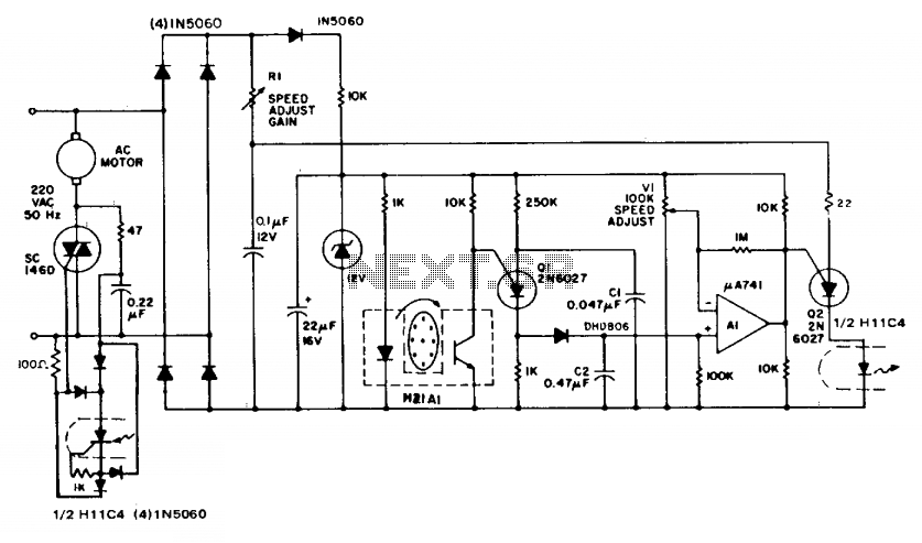
The circuit demonstrates feedback speed regulation for a standard AC induction motor, a task that is typically challenging to achieve without the use of an expensive generator-type precision tachometer. When the apertured disc connected to the motor shaft allows...
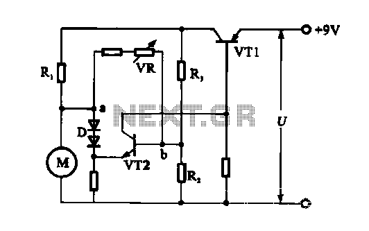
The electronic circuit for steady speed motor applications utilizes an automatic remote control system to regulate the motor power supply, thereby achieving consistent speed control. The circuit diagram illustrates a DC motor connected to the system. Given that the...

The first schematic page contains the primary content of the design, while the second page features simulation support circuitry. The primary design controls the accessory relays and indicators. It also drives the control loop and adjusts the throttle control...
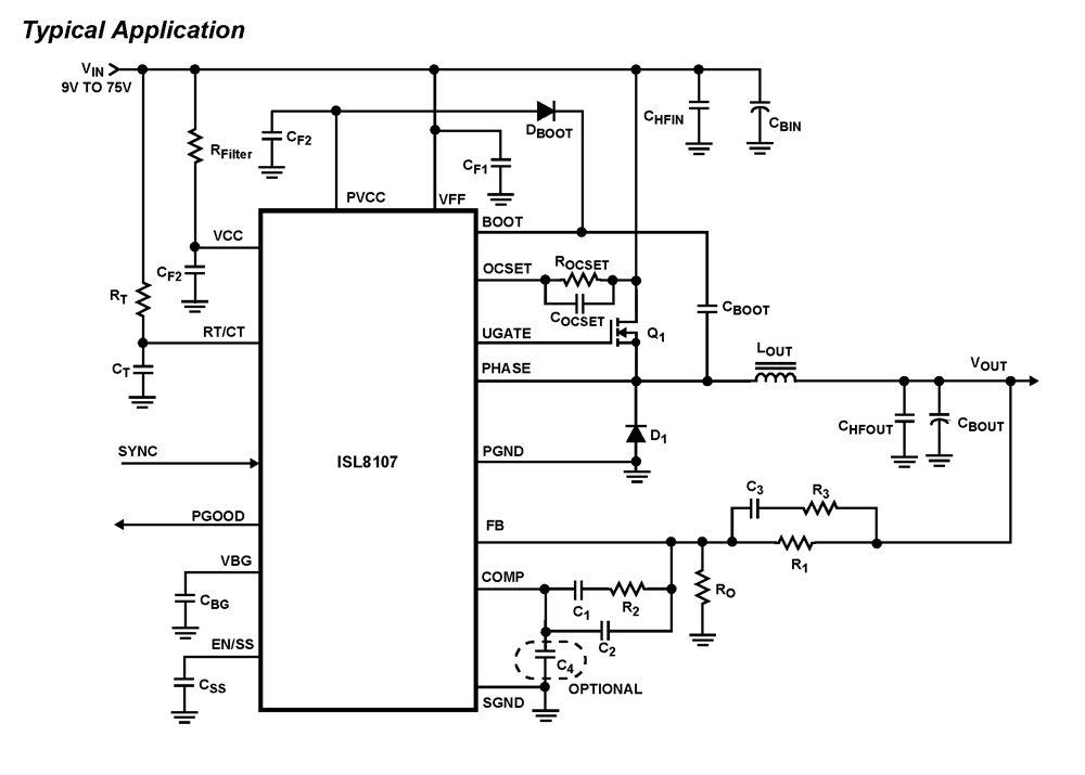
The ISL8107 is a single-phase, non-synchronous buck controller equipped with an integrated high-side MOSFET driver. It operates within an input voltage range of 9V to 75V. The internal reference voltage is 1.192V with a tolerance of ±1% across the...