
motorola hi fi power
To ensure optimal performance of the amplifier circuit, it is crucial to accurately measure the hfe values of the transistors T3 and T4. The hfe, or current gain, is a vital parameter that influences the overall gain and fidelity of the amplifier. When selecting transistors, a tolerance of less than 30% between the hfe values is recommended to maintain sound clarity. The use of MJ3001 and MJ2501 transistors, known for their reliability in audio applications, resulted in a minimal deviation of approximately 5%, which is acceptable for high-quality sound reproduction.
Prior to powering the amplifier, it is essential to short-circuit the input to prevent any unwanted signals from affecting the initial measurements. Connecting a milliampere meter to the output allows for precise monitoring of the DC output current. Upon powering the amplifier, the R13 potentiometer must be adjusted carefully. This adjustment is critical for minimizing the DC offset at the output, which could otherwise lead to distortion or damage to connected speakers. The goal is to achieve a DC output current as low as possible, ideally reaching zero. In this case, a successful adjustment was made, reducing the current to 10 microamperes, which indicates that the amplifier is functioning correctly without significant DC offset.
In summary, following these procedures ensures the amplifier operates within its designed specifications, contributing to clear and accurate sound reproduction. Proper transistor matching and meticulous adjustment of the output current are essential steps in the amplifier setup process.The first thing that you must do, is to measure the end transistors (T3 and T4) amplifying coefficient, the hfe or ². If their disagreement is bigger than 30 %, the amplifier would not give a clear sound. I used MJ3001 and MJ2501 transistors, and this disagreement was around 5%. - Before the first ½turning on ½ you must short circuit the input s of the amp, and put a mA-meter on the output, than turn the amplifier on, and tune the R13 pot, to decrease the DC current on the output, to some uA-s, or in a lucky situation to zero. I was able to decrease it to 10 uA. 🔗 External reference
Related Circuits
Here's a power-on time delay relay circuit that takes advantage of the emitter/base breakdown voltage of an ordinary bi-polar transistor. The reverse connected emitter/base junction of a 2N3904 transistor is used as an 8 volt zener diode which creates...
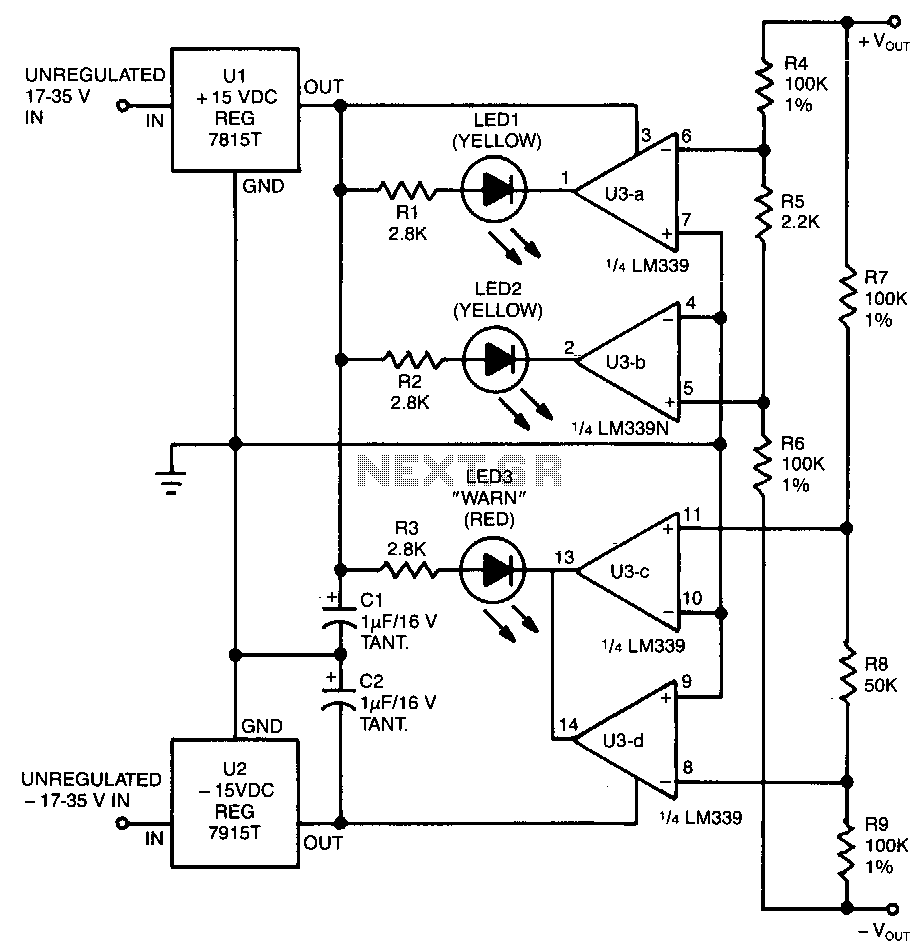
This circuit utilizes two pairs of comparators from an LM339N quad comparator. One pair controls the yellow positive (+) and negative (-) indicators, while the other pair drives the red warning LED3. The circuit is powered by the unregulated...

This is a circuit for Closed-Loop Automatic Power Control for RF Applications. The circuit utilizes a log detector (AD8318) and a variable gain amplifier (VGA) (ADL5330). The Closed-Loop Automatic Power Control (APC) circuit is designed to maintain a consistent output...
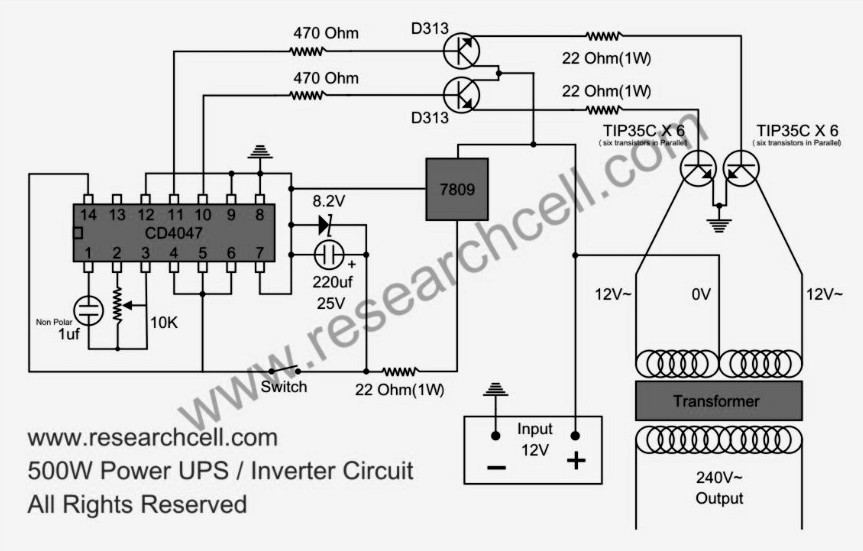
This circuit diagram features a single variable resistor utilized to adjust the frequency of a 240V AC output current. It is advisable to use a frequency meter to modify the frequency from 50Hz to 60Hz according to specific requirements....
I use the lm10 IC because it has a reference voltage and that’s useful for dc power supply. With two ICs can take different output voltage and amperage. This circuit is protected from short circuit. P2 is for controlling...
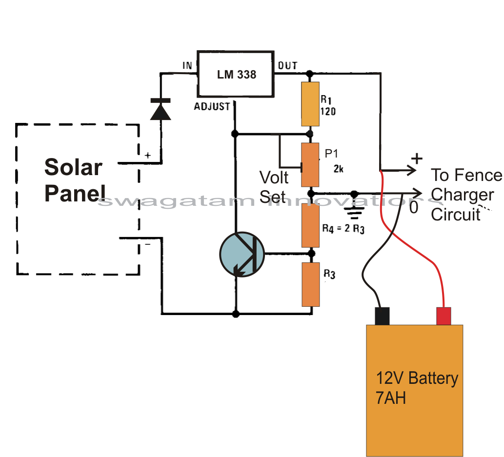
A fence charger, also known as an energizer, is a device used to electrify a fence or boundary to protect the enclosed area from human or animal intrusions. These boundaries are often located in large fields and parks, typically...
Warning: include(partials/cookie-banner.php): Failed to open stream: Permission denied in /var/www/html/nextgr/view-circuit.php on line 713
Warning: include(): Failed opening 'partials/cookie-banner.php' for inclusion (include_path='.:/usr/share/php') in /var/www/html/nextgr/view-circuit.php on line 713