
Dc servo bipolar control
The described circuit operates as a sophisticated control mechanism for managing the power delivered to a DC load, particularly in applications such as servo motors. The bipolar control input of ± 5 V provides the necessary versatility for various operational scenarios. The core of the design relies on two TMOS devices, Q1 and Q2, which are configured in an anti-series arrangement. This configuration allows for bidirectional current flow, crucial for applications requiring control over both directions of current.
The control strategy employed in this circuit enhances efficiency by utilizing the reverse bias condition of the TMOS devices. When Q1 and Q2 are reverse biased, they are activated by the control circuits, which effectively bypasses the inherent reverse rectification that would otherwise occur. This design choice significantly reduces power losses, making the circuit more efficient in its operation.
The AC power source is managed by the Q1-Q2 switch, which only connects to the load when the instantaneous AC voltage matches the polarity of the control voltage and remains below it. This selective connection is vital for ensuring that the load receives the appropriate voltage levels, thereby optimizing performance. The inclusion of U1A and U1B as rectifiers is essential; U1A allows for the passage of positive control voltages while U1B manages negative voltages, ensuring that the circuit responds correctly to the varying input conditions.
The operational logic for Q1 and Q2 is governed by the outputs of the rectifiers. U1C enables Q1 whenever the AC input voltage falls below the output of U1A, facilitating control during the positive half-cycle. Conversely, for negative control voltages, Q1 is engaged only during the negative half-cycle, allowing for precise timing in the application of power. Similarly, U1D governs Q2, activating it when the AC input voltage exceeds the output of U1B, thus ensuring that the circuit can effectively manage both halves of the AC waveform.
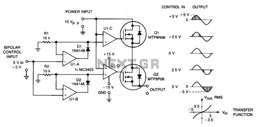
Overall, this circuit exemplifies a robust design for controlling DC loads with AC power, leveraging advanced semiconductor technology and efficient control strategies to achieve optimal performance.This circuit accepts bipolar control inputs of ± 5 V and provides a phase-chopped output to a dc load (such as a servo motor) of the same polarity as the input. The rms voltage of the output is closely proportional to the control input voltage. N-channel and p-channel TMOS devices', Ql and Q2, are connected in anti-series to form a bidirectional switch through which current can flow in either the forward or reverse direction.
Control circuits turn Ql and Q2 on when they are reverse biased, bypassing their reverse rectifier and increasing circuit efficiency. Each device is allowed to turn off only when forward biased. The Q1-Q2 switch connects the ac power source to the load when its instantaneous voltage is the same polarity and less than the control voltage. Ula is configured as an ideal positive rectifier whose output follows the control voltage when it is positive, and is zero otherwise.
Similarly, Ulb is a negative rectifier. Ulc turns Ql on whenever the ac input voltage is lower than the positive rectifier output. For negative control voltages, Ql is turned on only during the negative half-cycle. For positive control voltages, Ql is turned on during the end portions of the positive half-cycle. Similarly, Uld turns Q2 on whenever the ac input voltage is higher than the output of the negative rectifier. 🔗 External reference
Related Circuits
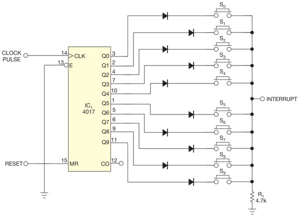
There are several methods to read multiple switch inputs using a reduced number of microcontroller unit (MCU) pins. One approach involves using an analog MCU pin to read multiple switches by assigning a unique voltage to each switch through...
The convenience of selecting TV channels using your remote and then pointing the same remote to your Computer so that you can control the whole system using the single remote control. The Following functions can be done with PC...
This circuit automatically controls the headlight of a motorcycle, turning it on and off independently of the light and ignition switches, as long as the battery is fully charged. The initial stage employs a 220-ohm resistor and ZD1 to...
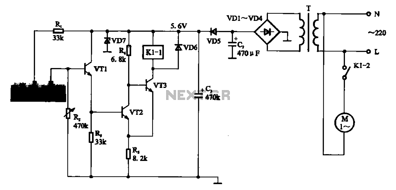
AC motor control circuit for a sprinkler. If the circuit involves an AC motor, it can be designed according to the connection shown in the figure, detailing the work process and the underlying principles of the circuit. The AC motor...
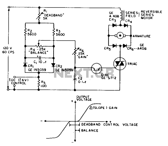
This is a positioning servo drive that includes adjustments for balance, gain, and deadband. In addition to receiving control from a DC signal, a mechanical input can be utilized for the balance control. Alternatively, this balance control can be...
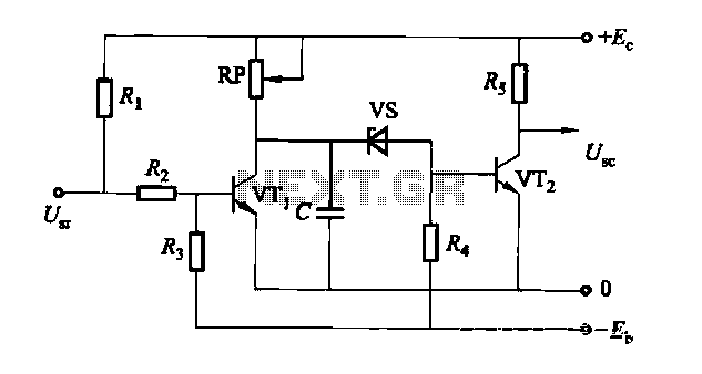
The circuit is a rechargeable short delay control for a conducting pipe, featuring two adjustment potentiometers (RP) that enable the delay time to be set from several hundred milliseconds to several seconds. The rechargeable short delay circuit is designed for...