
Infra-red Level Detectors
IC1 serves as an oscillator that drives the infrared LED, generating 0.8 ms pulses at a frequency of 120 Hz, with a peak current of about 300 mA. Diodes D1 and D2 are aligned facing the target, positioned a couple of centimeters apart on a short breadboard strip. D2 detects the infrared beam emitted by D1 and reflected from the surface in front of it. The received signal is amplified by IC2A and then peak detected by D4 and C4. Diode D3, along with resistors R5 and R6, compensates for the forward voltage drop of D4. A DC voltage, proportional to the distance of the reflecting object from D1 and D2, is fed into the inverting input of the voltage comparator IC2B. This comparator controls the LED and an optional relay via Q1, comparing its input voltage to a reference voltage set at the non-inverting input by trimmer R7. A regulated power supply is necessary, which is why IC3 is included, to ensure precise reference voltages. The circuit can be powered by a commercial wall plug-in power supply with a DC output voltage ranging from 12 to 24V. The infrared photodiode D2 should include an optical sunlight filter; these components typically come in black plastic cases and may resemble TO92 transistors. It is important to note that the sensitive surface is the curved side, not the flat side.
This liquid level or proximity detection circuit utilizes an infrared beam to measure distances effectively, making it suitable for various applications, including automated liquid level monitoring in tanks or containers. The circuit's design emphasizes non-contact measurement, which is advantageous in scenarios where contamination or interference with the liquid is a concern.
The operational principle relies on the reflection of infrared light; thus, the choice of transmitting and receiving LEDs is critical. The circuit's sensitivity can be fine-tuned for different applications by adjusting the trimmer, allowing for flexibility in detecting various liquid types or surfaces. The use of a regulated power supply ensures that the circuit operates reliably under varying load conditions, which is essential for consistent performance.
The configuration of the components, particularly the positioning of the infrared LED and photodiode, is crucial for maximizing the detection range and accuracy. The amplification stage is designed to enhance the weak signals received by the photodiode, ensuring that even minimal reflections can be detected and processed. The comparator stage provides a straightforward output mechanism, enabling easy integration with visual indicators like LEDs or control devices such as relays to manage larger loads.
Overall, this circuit represents a practical solution for liquid level detection, leveraging infrared technology to provide accurate, reliable, and safe measurements without direct contact with the liquid being monitored. Its design can be adapted for various applications across different industries, enhancing automation and control processes.This circuit is useful in liquids level or proximity detection. It operates detecting the distance from the target by reflection of an infra-red beam. It can safely detect the level of a liquid in a tank without any contact with the liquid itself. The device`s range can be set from a couple of cm. to about 50 cm. by means of a trimmer. Range can v ary, depending on infra-red transmitting and receiving LEDs used and is mostly affected by the color of the reflecting surface. Black surfaces lower greatly the device`s sensitivity. IC1 forms an oscillator driving the infra-red LED by means of 0. 8mSec. pulses at 120Hz frequency and about 300mA peak current. D1 & D2 are placed facing the target on the same line, a couple of centimeters apart, on a short breadboard strip.
D2 picks-up the infra-red beam generated by D1 and reflected by the surface placed in front of it. The signal is amplified by IC2A and peak detected by D4 & C4. Diode D3, with R5 & R6, compensate for the forward diode drop of D4. A DC voltage proportional to the distance of the reflecting object and D1 & D2 feeds the inverting input of the voltage comparator IC2B. This comparator switches on and off the LED and the optional relay via Q1, comparing its input voltage to the reference voltage at its non-inverting input set by the Trimmer R7.
Power supply must be regulated (hence the use of IC3) for precise reference voltages. The circuit can be fed by a commercial wall plug-in power supply, having a DC output voltage in the range 12-24V. The infra-red Photo Diode D2, should be of the type incorporating an optical sunlight filter: these components appear in black plastic cases.
Some of them resemble TO92 transistors: in this case, please note that the sensitive surface is the curved, not the flat one. 🔗 External reference
Related Circuits
This circuit is an Audio Decibel Level Meter that utilizes the SA604 integrated circuit, which is designed as an RF device and also serves as a Received Signal Strength Indicator (RSSI). In cellular radio applications, the radio's microcomputer continuously...
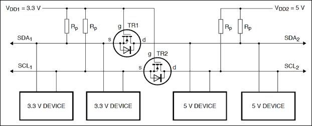
Construct a logic level shifter using discrete components such as transistors and resistors, or opt for a single-component solution with an integrated circuit (IC). Many ICs do not accept input voltages as low as 1.4 V; however, the Fairchild...
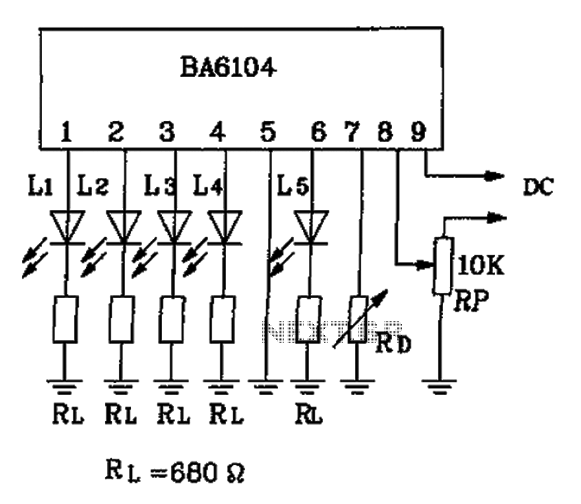
The BA6104 is a five-digit LED level meter driver integrated circuit (IC) used in basic application circuits. When the input level exceeds the required display threshold of 1V, only 7 feet of the power supply Vcc are indirectly affected...
This circuit will emit an intermittent beep (or will flash a LED) when the water contained into a recipient has reached the desired level. It should be mounted on top of the recipient (e.g. a plastic tank) by means...
The sensitivity of the gate terminal to voltage changes is significant. In this configuration, the gate terminal is left open circuit and connected only to a probe, which consists of a few inches of bare copper wire. Without a...

Three power levels are provided by the two logic inputs of this enhanced circuit. R5, D4, D5, and O2 create a power supply for the logic integrated circuit. These components can be excluded if an alternative low voltage source...