
Delay Loops

The flashing LED circuit utilizes a microcontroller programmed to execute a series of instructions that control the LED’s state. The microcontroller operates at a clock frequency of 4 MHz, which results in an instruction execution time of 1 microsecond (µs). The rapid execution of five instructions leads to a total LED toggle time of merely 5 µs, which is imperceptible to the human eye, causing the LED to appear continuously illuminated.
To introduce a visible delay between the LED's on and off states, a countdown mechanism is implemented. A constant named COUNT is defined, which serves as a counter. The maximum value for COUNT is set to 255 (or 0xFF in hexadecimal), which corresponds to the maximum value that can be stored in an 8-bit register. The equ instruction is used to associate COUNT with a specific register address, such as 0x08, ensuring that it points to a general-purpose register.
To modify the value of COUNT, a specific value is moved into the designated register. For instance, moving the hexadecimal value 0x55 into the register will set COUNT to 85. The program then employs the `decfsz` instruction, which decrements the value of COUNT by 1 and checks if it has reached zero. If COUNT is not zero, the program continues executing instructions sequentially. If COUNT does equal zero, execution jumps to the specified label, effectively creating a delay loop.
This delay loop allows the program to pause for a predetermined time, thus making the LED flash visible. Multiple loops can be chained together to extend the duration of the delay as needed. The final instructions in the program include moving the value of the working register to PORTA, which controls the LED's state, and utilizing a loop to repeat the flashing cycle.
The schematic for this circuit will typically include the microcontroller, the LED, and necessary current-limiting resistors. The LED is connected to one of the microcontroller's output pins, while the program is loaded onto the microcontroller to execute the LED flashing sequence. This project serves as an introductory exercise in programming microcontrollers and understanding basic electronic principles.There is one slight drawback to our flashing LED program. Each instruction takes one clock cycle to complete. If we are using a 4MHz crystal, then each instruction will take 1/4MHz, or 1uS to complete. As we are using only 5 instructions, the LED will turn on then off in 5uS. This is far too fast for us to see, and it will appear that the LED is perma nently on. What we need to do is cause a delay between turning the LED on and turning the LED off. The principle of the delay is that we count down from a previously set number, and when it reaches zero, we stop counting. The zero value indicates the end of the delay, and we continue on our way through the program. So, the first thing we need to do is to define a constant to use as our counter. We will call this constant COUNT. Next, we need to decide how big a number to start counting from. Well, the largest number we can have is 255, or FFh in hex. Now, as we mentioned in the last tutorial, the equ instruction assigns a word to a register location.
This means that whatever number we assign our COUNT, it will equal the contents of a register. If we try and assign the value FFh, we will get an error when we come to compile the program. This is because location FFh is reserved, and so we can`t access it. So, how do we assign an actual number Well, it takes a little bit of lateral thinking. If we assign our COUNT to the address 08h, for example, this will point to a general purpose register location. By default, the unused locations are set to FFh. Therefore, if COUNT points to 08h, it will have the value of FFh when we first switch on. But, We hear you cry, how do we set COUNT to a different number Well, all we do is move` a value to this location first.
For example, if we wanted COUNT to have a value of 85h, we can`t say COUNT equ 85h because that is the location of out Tri-State register for Port A. What we do is this: Next we need to decrease this COUNT by 1 until it reaches zero. It just so happens that there is a single instruction that will do this for us, with the aid of a goto` and a label.
The instruction we will use is: This instruction says Decrement the register (in this case COUNT) by the number that follows the comma. If we reach zero, jump two places forward. ` A lot of words, for a single instruction. Let us see it in action first, before we put it into our program. What we have done is first set up our constant COUNT to 255. The next line puts a label, called LABEL next to our decfsz instruction. The decfsz COUNT, 1 decreases the value of COUNT by 1, and stores the result back into COUNT. It also checks to see if COUNT has a value of zero. If it doesn`t, it then causes the program to move to the next line. Here we have a goto` statement which sends us back to our decfsz instruction. If the value of COUNT does equal zero, then the decfsz instruction causes our program to jump two places forward, and goes to where We have said Carry on here`.
So, as you can see, we have caused the program to stay in one place for a predetermined time before carrying on. This is called a delay loop. If we need a larger delay, we can follow one loop by another. The more loops, the longer the delay. We are going to need at least two, if we want to see the LED flash. movwf PORTA ;it into the w register and then ;on the port goto Loop1 ;Go back to the start of our loop.
;This delay counts down from ;255 to zero, 255 times movwf PORTA;it into the w register and then on ;the port goto Start ;go back to Start and turn LED ;on again You can compile this program and then program the PIC. Of course, you will want to try the circuit out to see if it really does work. Here is a circuit diagram for you to build once you have programmed your PIC. Congratulations, you have just written your first PIC program, and built a circuit to flash an LED on and off.
So far, if you have followed these tutorials, you have learnt a total of 7 instru 🔗 External reference
Related Circuits
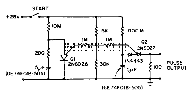
The circuit reduces the effective peak current of the output PUT, Q2. It allows the capacitor to charge with a high gate voltage and periodically lowers the gate voltage. When Q1 fires, the timing resistor can be set to...
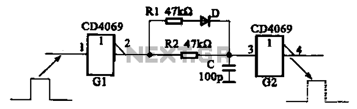
The inverter circuit using CD4069 is configured with a delay and width adjustment. When the output of the inverter (G1) is high, the capacitor (C) charges through resistor (R1) and diode (D). The voltage across capacitor C quickly reaches...
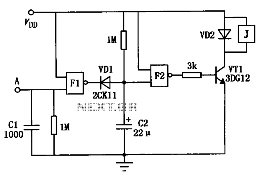
The touch delay switch, as illustrated in the figure, is composed of a CMOS NAND gate and is capable of providing a delay of approximately 10 seconds. It is commonly utilized for the automatic control of lighting in street...
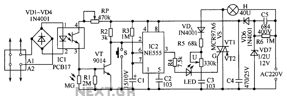
The telephone table lamp is designed to automatically illuminate during night ringing or when the phone is off-hook. After hanging up, the lamp will extinguish after a delay of 45 seconds. It is typically used as a general-purpose lamp...
The two circuits demonstrate the process of opening a relay contact shortly after the ignition or light switch is turned off. The capacitor becomes charged, and the relay remains closed until the voltage at the diode anode reaches +12...
In this circuit, an LM339 quad voltage comparator is utilized to generate a time delay and control a high current output at low voltage. Approximately 5 amps of current can be sourced using a pair of fresh alkaline D...