
Long range FM transmitter

The transmitter circuit operates primarily in the VHF range, utilizing a variable-frequency oscillator to generate the desired radio frequency signals. The BF494 transistor, being a low-power device, is adept at generating frequencies in the VHF spectrum while maintaining stability. The inclusion of a varicap diode allows for fine-tuning of the frequency, enabling dynamic adjustments based on input audio signals for modulation purposes.
The power amplification stage, employing the 2N3866 transistor, is critical for enhancing the output signal to a level suitable for effective transmission. This transistor is designed for high-frequency applications and can handle the power levels required for this transmitter, ensuring that the output remains within the specified range of 200-250 milliwatts. The power gain of four to five times is essential for achieving the desired range of up to 2 kilometers, contingent on the efficiency of the antenna system.
The circuit's design emphasizes the importance of housing and shielding to minimize interference and enhance performance. Utilizing a glass epoxy board for assembly ensures durability and reduces the risk of circuit failure due to environmental factors. The aluminum case not only provides physical protection but also aids in heat dissipation, which is vital for maintaining the operational integrity of the power amplifier.
The adjustments provided by potentiometers VR1 and VR2 allow for user customization of both frequency and output power, which is essential for adapting to varying conditions and requirements. The recommendation to use a 12V rechargeable battery pack ensures that the circuit operates efficiently and reduces the risk of hum or noise, which can be detrimental to signal quality.
Overall, this transmitter circuit is a robust design suitable for various applications, including amateur radio and experimental setups, where reliable VHF transmission is desired. Proper assembly, adjustment, and adherence to the guidelines provided will yield a functional and effective transmitter capable of delivering good performance over significant distances.The transmitter circuit described here has an extra RF power amplifier stage, after the oscillator stage, to raise the power output to 200-250 milliwatts. With a good matching 50-ohm ground plane antenna or multi-element Yagi antenna, this transmitter can provide reasonably good signal strength up to a distance of about 2 kilometres.
The circuit b uilt around transistor T1 (BF494) is a basic low-power variable-frequency VHF oscillator. A varicap diode circuit is included to change the frequency of the transmitter and to provide frequency modulation by audio signals. The output of the oscillator is about 50 milliwatts. Transistor T2 (2N3866) forms a VHF-class A power amplifier. It boosts the oscillator signals` power four to five times. Thus, 200-250 milliwatts of power is generated at the collector of transistor T2. For better results, assemble the circuit on a good-quality glass epoxy board and house the transmitter inside an aluminium case.
Shield the oscillator stage using an aluminium sheet. Potentiometer VR1 is used to vary the fundamental frequency whereas potentiometer VR2 is used as power control. For hum-free operation, operate the transmitter on a 12V rechargeable battery pack of 10 x 1. 2-volt Ni-Cd cells. Transistor T2 must be mounted on a heat sink. Do not switch on the transmitter without a matching antenna. Adjust both trimmers (VC1 and VC2) for maximum transmission power. Adjust potentiometer VR1 to set the fundamental frequency near 100 MHz. 🔗 External reference
Related Circuits
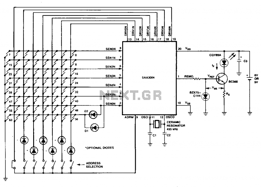
The transmitter keyboard is organized as a scanned matrix consisting of 7 driver outputs and 7 sense inputs. The driver outputs, labeled DRVON to DRV6N, are open-drain n-channel transistors that remain conductive in standby mode. The 7 sense inputs,...
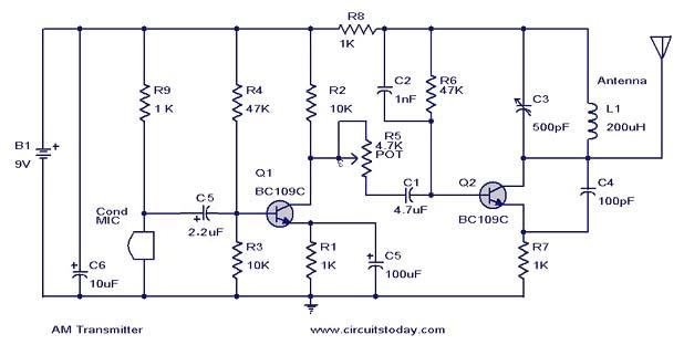
This document presents a circuit diagram of a simple AM transmitter that is capable of transmitting audio signals to a specified area. The circuit is designed with a limited power output to comply with FCC regulations while effectively producing...
CW is the simplest form of modulation. The output of the transmitter is switched on and off, typically to form the characters of the Morse code. CW transmitters are simple and inexpensive, and the transmitted CW signal doesn’t occupy...
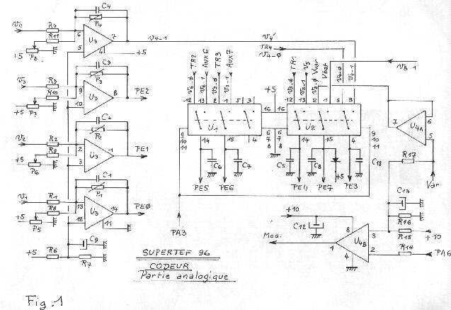
The first SUPERTEF version was using a 68HC11 microprocessor in extended mode i.e. with an external memory program which necessitated many integrated circuits (IC) such as the 74C138, 74C373, 68HC24 and 27C64 making the printed circuit board densely populated...
The RF oscillator utilizes inverter N2 and a 10.7 MHz ceramic filter to drive the parallel combination of inverters N4 to N6 through inverter N3. Since these inverters are connected in parallel, the output impedance is low, allowing direct...
This is a simple design of a small FM transmitter bug that is ideal for transmitting and eavesdropping purposes. Due to its high sensitivity, it can even pick up the ticking of a clock. The estimated range is approximately...