
AM transmitter
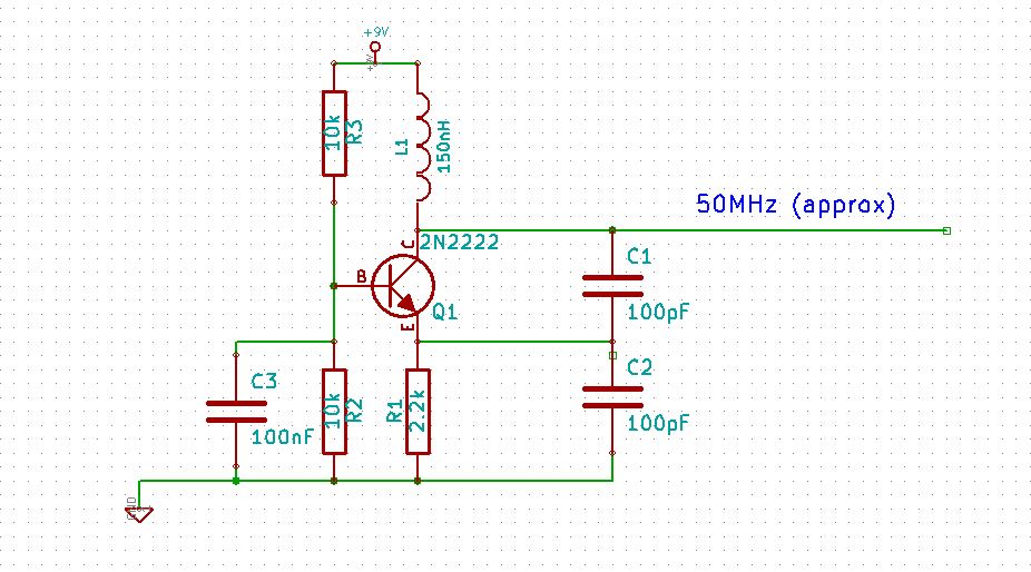
The Colpitts oscillator is a type of electronic oscillator that utilizes a combination of capacitors and an inductor to create an oscillating signal. The tank circuit in a Colpitts oscillator is critical for determining the frequency of oscillation, which can be calculated using the formula:
\[ f = \frac{1}{2\pi\sqrt{LC}} \]
where \( L \) is the inductance and \( C \) is the effective capacitance of the capacitors in the circuit. This oscillator configuration is particularly valued for its simplicity and effectiveness in generating sine waves, making it suitable for applications where signal purity is essential.
When designing the circuit, it is important to select components that minimize power consumption while ensuring the output signal meets the desired specifications. Utilizing an AM radio frequency that is less congested can help reduce the likelihood of interference with other radio services. Additionally, the output power should be kept at a level that allows for local transmission without causing disruption to nearby electronic devices.
For applications requiring enhanced frequency stability, the Clapp oscillator can be considered. This variant employs a similar tank circuit but incorporates additional capacitance, which improves the oscillator's performance against variations in temperature and component tolerances. The Clapp oscillator is particularly useful in scenarios where precise frequency control is necessary.
Alternatively, for generating signals at specific frequencies such as 1 kHz, the Wien bridge oscillator is recommended. This oscillator does not rely on inductive components, which simplifies the design and can lead to improved performance in certain applications. The Wien bridge oscillator uses a bridge circuit with resistors and capacitors to establish the desired frequency of oscillation.
Overall, careful consideration must be given to the choice of oscillator type, frequency selection, and power output to ensure compliance with regulatory standards and to minimize the potential for interference with existing radio services.As with your square wave, you will interfere with people`s radios, & they will become quite upset, plus you may attract the attention of the licencing authority-& believe me, you don`t want that! you need I believe a colpits oscilator, this will have a "tank circuit" in it that is the Lc part and will produce a sine wave.
Use only as much power as you need. I`d suggest one of the frequencies used by AM radio as they are seldom used and just enough power to transmit as far as you need. you need I believe a colpits oscilator, this will have a "tank circuit" in it that is the Lc part and will produce a sine wave.
Use only as much power as you need. I`d suggest one of the frequencies used by AM radio as they are seldom used and just enough power to transmit as far as you need. well due the the not excellent coverage in the UK most are forced to listen to the radio via the internet.
I guess that is why we are having to scale up our internet network - just so we can listen to the godamn radio My paramount suggestion is keep the power as low as possible, if it is just a carrier it should not upset reception to other devices too much unless they are the same distance as the intended receiver (5 meters ) I would go for a clapp oscillator as they are a bit more stable than the colpitts but if you only want a 1khz signal a wein bridge circuit would be better as no inductance is required. There are reasons why people don`t just choose frequencies at random to do stuff, & that is because the Radio Spectrum is already allocated to various services, who don`t want your little "drifty" oscillator to interfere with them!
🔗 External reference
Related Circuits
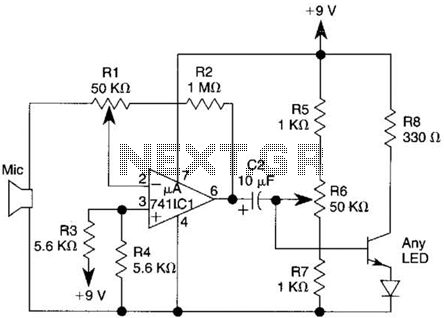
This transmitter utilizes a 741 operational amplifier as a high-gain audio amplifier, which is activated by a microphone. The output of the 741 is connected to Q1, functioning as the driver for an LED. Potentiometer R1 serves as the...
Long-range FM transmitter. The power output of most of these circuits is very low because no power amplifier stages were incorporated. The transmitter circuit described here has an. The long-range FM transmitter operates by modulating a carrier frequency with an...
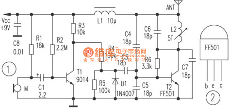
The circuit depicted utilizes a specialized launch tube T2 along with its associated components to create a high-frequency oscillator operating within the frequency range of 88 to 108 MHz. An electret microphone captures the audio signal, which is subsequently...

A high-quality QRP transmitter, named NEXUS 6, is designed to explore issues related to extremely narrow bandwidth communication. This device is not merely a simplified version of a QRP transmitter; it aims to create a cost-effective system that can...
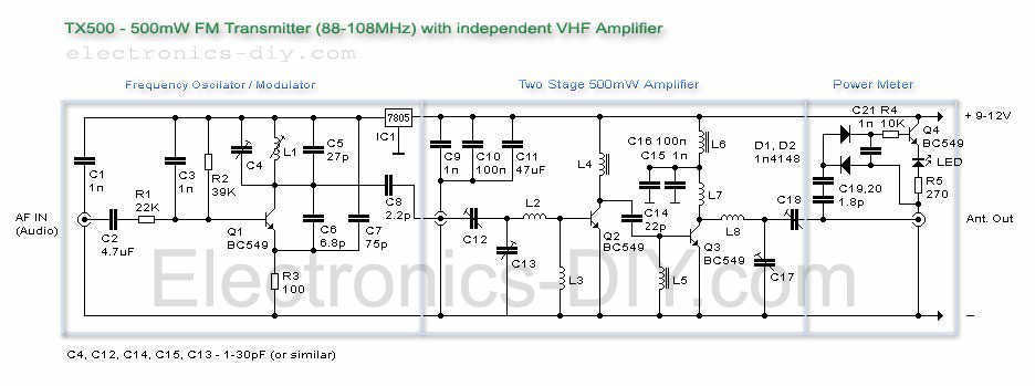
The TX500 is a simple to build 500mW FM Transmitter. It consists of three blocks: modulator/oscillator, two-stage 500mW VHF amplifier, and LED-based power meter. The TX500 allows transmitting audio signals to the FM band at frequencies from 88 MHz...
The transmitter circuit described here includes an additional RF power amplifier stage following the oscillator stage, which increases the power output to 200-250 milliwatts. When used with a properly matched 50-ohm ground plane antenna or a multi-element Yagi antenna,...