
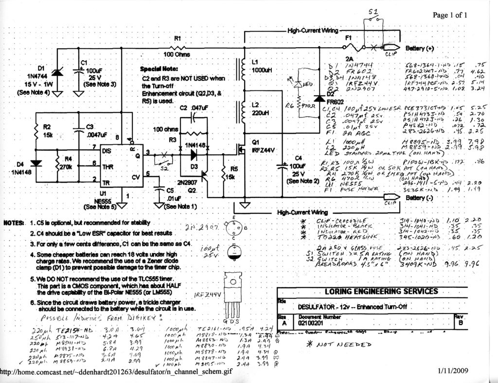
Desulfator for 12V Car Batteries
The project aims to design an electronic circuit that incorporates various components to achieve a specific functionality. The schematic will typically include a power supply section, signal processing units, and output stages, depending on the intended application.
The power supply section can consist of a transformer, rectifier, and voltage regulator to ensure a stable power output. This section is crucial for providing the necessary voltage and current levels required by the circuit.
The signal processing units may include operational amplifiers, filters, and analog-to-digital converters (ADCs). These components are responsible for manipulating the input signals, enhancing signal quality, and converting analog signals into digital form for further processing.
The output stage of the circuit can involve drivers, transistors, or relay switches, depending on whether the output is intended for a load or for further signal transmission. Proper selection of these components is essential to ensure that the output meets the required specifications for the application.
In summary, creating a personal electronic project involves careful planning and selection of components that work together to fulfill the desired functionality while ensuring reliability and performance.Hello Everybody! After a year or so of reading and drooling over other people`s wonderful projects in these pages I decided to finally make one of my.. 🔗 External reference
Related Circuits
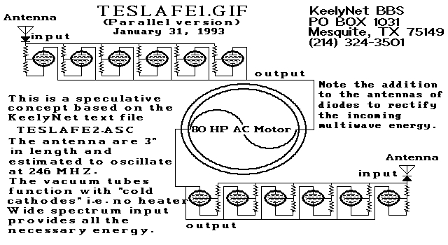
Two schematic diagrams illustrate a series and a parallel circuit configuration that Tesla may have utilized. The components featured are the 70L7GT Half Wave Rectifier tubes, which are surprisingly still available today. While there is an interest in accessing...
this circuit uses the LM3914 and should be powered by its own battery, otherwise you might get an inaccurate reading. hook the to-be-monitored battery to pin 5 of the chip. More: all resistors are 5 or 10 percent tolerance,...
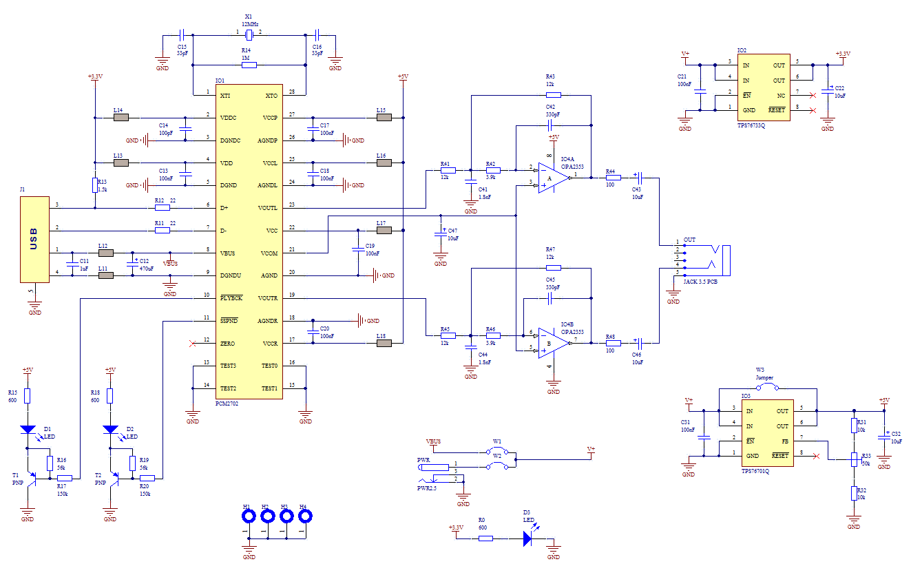
The core of this construction is 16-Bit Stereo Digital-To-Analog Converter with USB interface PCM2702. PCM2702 needs only a few additional parts to work. The schematic is not complex. The sound card can be powered directly from the USB port...

This is a stereo audio amplifier designed for automotive applications. The circuit utilizes a single integrated circuit, the TDA1553, along with several external components. This IC is responsible for managing the stereo audio system in a vehicle. The TDA1553CQ...
When the door is opened, SW1 closes, powering the circuit and turning on the lamp. C1 begins to charge slowly through R1, and when the voltage at pins #2 and #6 of IC1 reaches 2/3 of the supply voltage,...
If the amp is built on bipolar transistors, and the preamp/crossover on FETs, then they were designed by different guys, right? Not this amp. Here, a strong, experienced designer's hand is evident from schematic to parts layout, PCB routing...