
USB Sound Card
During the review, it was noted that the PCM2702 is no longer recommended for new designs, but TI offers even better solutions. PCM2704 and PCM2705 provide the same functionality as PCM2702 but include an output filter and can drive headphones directly. Volume and mute can be controlled through SPI bus in PCM2705 or with pushbuttons in PCM2704. PCM2704 and PCM2705 are available in TSSOP28 packages. PCM2706 is similar to PCM2704, and PCM2707 is similar to PCM2705, but both include an I2S bus. PCM2706 and PCM2707 are available in TQFP32 packages. It is recommended to use these new chips for new designs.
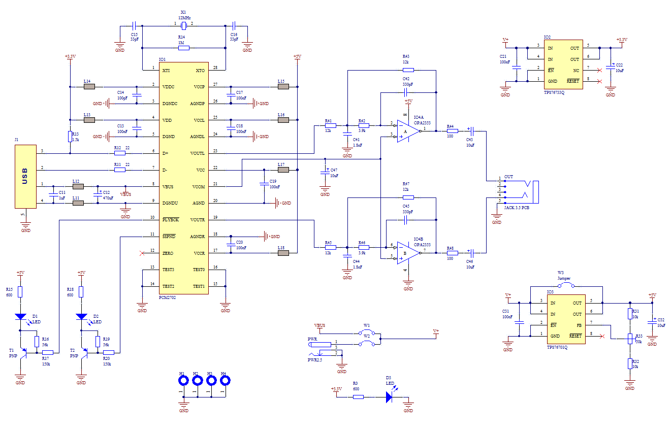
The schematic for this sound card design incorporates a PCM2702 Digital-To-Analog Converter, which is the central component that converts digital audio signals from a USB source into analog signals suitable for audio output. The power supply section is critical, utilizing two low-dropout (LDO) regulators: the TPS76733Q for the 3.3V rail, which is essential for the digital logic of the PCM2702, and the TPS76701Q for the 5V rail, which powers the analog circuitry. The configuration of the LDOs ensures stable voltage levels necessary for optimal performance and minimizes noise on the power lines.
The addition of ferrite beads on the power lines serves to filter out high-frequency noise, which is crucial in audio applications to maintain signal integrity. The low-pass filter implemented using the OPA2353UA op-amp is designed to eliminate high-frequency artifacts from the digital-to-analog conversion process, ensuring that only the desired audio frequencies are passed to the output.
LED indicators provide feedback on the operational status of the sound card, with D1 signaling active audio playback and D2 indicating when audio transmission is suspended. The ability to easily switch between USB power and an external power supply adds versatility to the design, accommodating different use cases.
In conclusion, while the PCM2702 is functional and has been validated across multiple operating systems, newer alternatives such as the PCM2704 and PCM2705 offer enhanced features and should be considered for future designs. These newer components simplify the circuit by integrating output filters and provide additional control options, thereby improving the overall design efficiency and performance.The core of this construction is 16-Bit Stereo Digital-To-Analog Convertor with USB interface PCM2702. PCM2702 needs only few additional parts to work. The schematic is not complex. Sound card can be powered directly from USB port (jumper W1) or from external power supply (jumper W3).
PCM2702 needs two power supply 3.3V (3V-3.6V) and 5V (4.5V-5.5V). I used fixed output voltage LDO TPS76733Q for 3.3V (IO2) and adjustable output voltage LDO TPS76701Q for 5V (IO3). Both LDO are produced by TI, I used this because I had it in my drawer. Any similar LDO can be used. Output voltage of IO3 should be set to little bit lower than input voltage to allow LDO good stabilization, in my case output voltage is set to 4.8V.
Output voltage can be set by adjustable resistor R33. In case of low power supply, IO3 can be shorted by jumper W3. LED D3 signalizes power on. Small ferrite beads are placed before all power pins of PCM2702 and in Vbus and GND of USB. These small beads reduce high frequency hum. I had a problem find this small SMD ferrite beads in local stores but finally I acquire few of them from old hard drive. They are not absolutely necessary, you can use zero ohm resistors instead of them. Low-pass filter is placed in output signal path to reduce sampling frequency. An OPA2353UA dual op amp is configured as a stereo 2nd-order low-pass filter. Led diode D1 is illuminated when PCM2702 plays audio data received from the USB bus. Led diode D2 is illuminated when USB bus suspends audio data transmission to the PCM2702. This circuit works very well. I only shorted crystal during soldering so the circuit didn?t work, but after removing the short the sound card started to work.
I have tested in Windows 2000, XP and Vista. It works in all mentioned systems. Drivers are present in operation system so the sound card is ready in few seconds after you connect it. During writing this article I have found that PCM2702 is now not recommended for new design, but TI offer even better solution.
PCM2704, PCM2705 have same functionality as PCM2702, but they include output filter. They are able to drive directly headphones. Volume and Mute can be controlled through SPI bus in PCM2705 or with pushbuttons in case of PCM2704. PCM2704 and PCM2705 are in TSSOP28 package. PCM2706 is similar to PCM2704 and PCM2707 to PCM2705 but in addition they have I2S bus. PCM2706 and PCM2707 are in TQFP32 package. I recommend using these new chips for new design (look at the TI web page). 🔗 External reference
Related Circuits
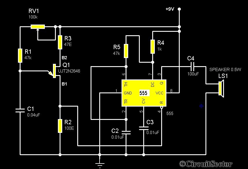
The circuit diagram illustrates a timer 555-based rain sound generator. It requires a 9V DC power supply, which can be provided by a 9V battery. The circuit utilizes a 0.5W, 8-ohm speaker to produce sound. When powered by a...
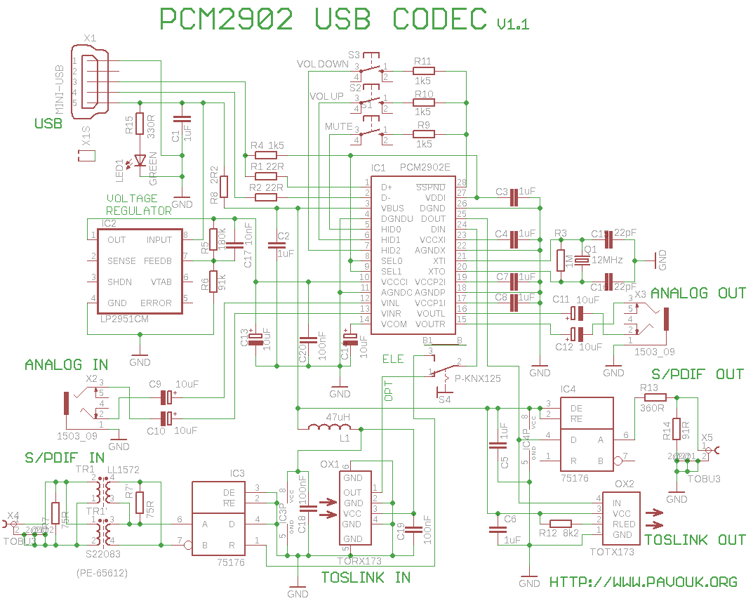
This is a USB sound card featuring the PCM2902 chip. It was designed to test the D/A converters and includes a simple circuit based on the PCM2902. The sound card is equipped with analog input and output, an electrical...

This design uses a smart card to enable a relay. A Nutchip recognizes its mating smart card among thousand similar ones, because you choose the code to be programmed in the card's memory. No specialized knowledge is necessary, as...
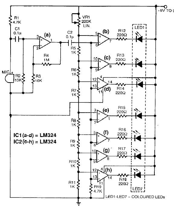
This sound level meter circuit can be used to control the intensity of a sound recording or in a disco. It has 5 measurement domains between 70 and 120 dB. The sound level meter circuit is designed to measure sound...
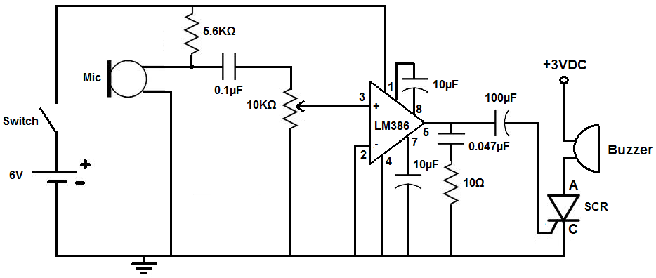
This circuit is designed to activate an alarm when it detects sound above a specified threshold. The alarm serves as a notification for any sound in areas that are typically quiet, such as quiet zones. Under normal quiet conditions,...
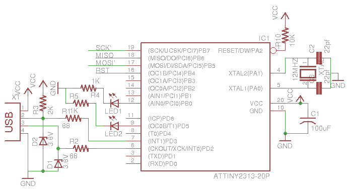
This is a low-cost AVR programmer using the ATtiny2313. The schematic diagram is provided below. First, set up the circuit as shown. One important consideration is to configure the fuse bits using the command: avrdude -c usbasp -p t2313...