
Motion Detector
The motion detector circuit is designed to provide real-time detection of movement through a combination of infrared technology and a robust signal processing mechanism. The infrared emitting diode serves as the primary source of the infrared beam, which is essential for detecting interruptions caused by moving objects. The MRD821 sensor is sensitive to changes in the infrared light intensity, allowing it to output a high voltage when the beam is intact and a low voltage when the beam is interrupted.
The integration of the 555 timer is crucial for amplifying the sensor's output, converting the analog signal variations into a digital format suitable for further processing. The 555 timer operates in a comparator mode, where the voltage levels at its input pins determine the output state. When the infrared beam is continuous, the output remains low, indicating no motion. However, when an object crosses the beam, the output transitions to high, triggering the subsequent actions in the program.
The interfacing of the motion detector with a computer through the printer port allows for easy integration into various applications, such as security systems or automated lighting controls. The software component is responsible for monitoring the sensor outputs in real-time. The provided code snippet illustrates a function that checks the status of the sensors, incrementing the trigger count when at least two sensors detect motion. This ensures that false positives are minimized, as simultaneous activation of multiple sensors is required to confirm motion.
Overall, the motion detector circuit exemplifies a practical application of infrared technology combined with electronic signal processing, facilitating reliable detection of movement in a variety of environments. The addition of a de-amplifier can enhance the circuit's performance by stabilizing the output voltage levels, ensuring compatibility with digital systems.The motion detector circuit consists of two components, the emitter and the sensor/detector. The emitter is simply made up of an infrared emitting diode reverse biased to a 5-volt source. The sensor uses the MRD821 to detect the IR beam from the emitter. It outputs a high of around 9 to 10-volts when the IR beam shines directly to it. If the beam is cut, it outputs a low of around 0. 4 to 2-volts. This signal is fed into pins 2 and 6 of a 555 timer, which in turn outputs the amplified signal at pin 3. The output is a TTL low when the IR beam is continuous and TTL high when the beam is cut. (Actually, outputs of about 6 to 7-volts are sometimes measured. A de-amplifier could be added at the end of the circuit to make sure the output does not exceed TTL levels.
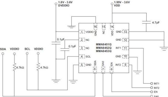
) The schematic diagram of both emitter and detector are shown in figure 1. There are three pairs of such sensors interfaced to the computer through the printer port. In order for motion to be sensed, a moving object must simultaneously trigger at least two of the detectors signifying that it has moved from one point to another. If the sensors have established motion, the controlling program proceeds to the appropriate routine. // IR Array Program Driver Program // Decoding is done via software int irmotion(){ int count=0, trigger=0, sensor=0; //initialize trigger & count flag int motion[3]={0x00, 0x00, 0x00}; //initialize array for sensor status outportb(0x37a, 0x08); //get mux`s attention outportb(0x37a, 0x08); //get mux`s attention do{ sensor=0; sensor=inportb(0x379); //get value at this port sensor=sensor & 0x70; //mask it motion[0]=sensor & 0x10; //assign status of each sensor motion[1]=sensor & 0x20; //as an element in motion array motion[2]=sensor & 0x40; if(motion[0]=0x10){ //at least 2 sensors must be triggered if(motion[1]=0x20 | motion[2]=0x40) //detect motion trigger+; } if(motion[1]=0x20){ if(motion[0]=0x10 | motion[2]=0x40) trigger+; //if motion is detected, trigger flag is incremented } if(motion[2]=0x40){ if(motion[0]=0x10 | motion[1]=0x20) trigger+; } count+; //increment count every pass to this function delay(30); }while(count!=2 && trigger!=2); return trigger; //if trigger=2, main function should //go to routine that deals with presence of intruder }
🔗 External reference
Related Circuits
This circuit can be used as an infrared beam barrier as well as a proximity detector. The circuit uses the very popular Sharp IR module (Vishay module can also be used). The pin numbers shown in the circuit are...
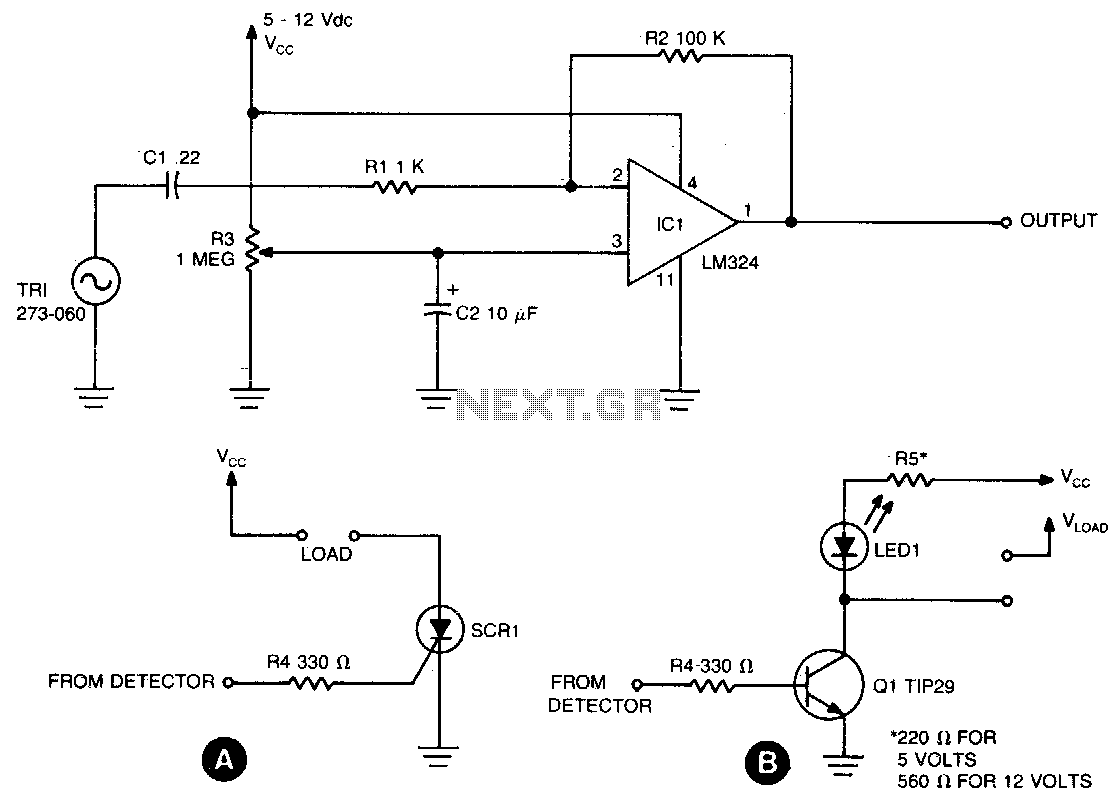
The sensing circuit is designed to detect both steady and fluctuating air flows. It utilizes a Radio Shack piezo buzzer (P/N 273-060) as its core component, along with an LM324 quad op-amp. The red wire from the piezo element...
Men often appreciate the convenience of television remote controls, which can sometimes frustrate their female partners. They tend to switch channels frequently, wanting to ensure they do not miss anything while a specific program is on. With the remote...
The task involved implementing and programming all hardware devices to make data accessible to the receiver program running on a PC. This included configuring all Prospeckz devices and establishing protocols for radio transmission communication back to the PC. Additionally,...
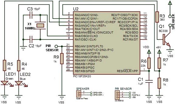
This project utilizes the PIC18F25K20 microcontroller to detect changes in a sensor's state and emit sound from a speaker or piezo buzzer. The microcontroller also monitors the battery voltage during startup. The algorithm is straightforward, employing an interrupt-on-change mechanism...
This schematic diagram illustrates a water level sensor, detector, and monitor circuit. An alarm is also integrated into this circuit. It is designed to detect any fluid with a resistance below 900K ohms. The water level sensor circuit typically employs conductive...