
Voltage-Controlled Current Sink
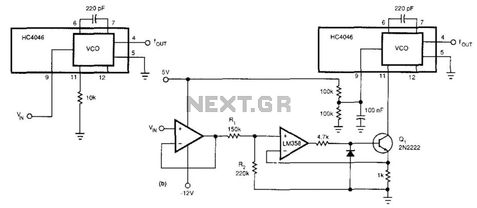
The circuit utilizes the HC4046 phase-locked loop (PLL) integrated circuit, which is designed for frequency synthesis and demodulation applications. By employing the LM358 operational amplifier as a constant-current sink, the circuit achieves a broader frequency span. This is critical for applications requiring precise frequency control and stability.
The LM358 is configured to provide a constant current, effectively replacing the traditional resistor in the frequency-determining network. The choice of a 10 kΩ resistor is standard for setting the frequency range, but by using the LM358, the circuit can maintain a consistent current regardless of temperature variations or supply voltage changes. This enhances the performance of the PLL by ensuring that the frequency remains stable over a wider range.
Pin 9 of the HC4046 is crucial as it determines the reference voltage for the frequency control. By holding this pin at a fixed 2.5 V, the circuit can operate within a defined voltage range, which is essential for achieving the desired frequency characteristics. This fixed voltage also helps in minimizing the effects of noise and fluctuations, leading to improved reliability and accuracy in frequency generation.
Overall, this configuration allows for a significant increase in the operational frequency range of the HC4046, making it suitable for more complex applications in communications, signal processing, and other electronic systems that require precise frequency modulation and demodulation capabilities. This circuit widens the linear frequency span of an HC4046 from one decade to nearly three decades. An LM35 8 is used as a constant-current sink to replace the frequency-determining resistor (10 kfl) from pin 9 to ground. Pin 9 is held at a fixed 2.5 V for this application. 🔗 External reference
Related Circuits
This page features H-Bridge circuits used for controlling direct current motors. Several designs are shown using both CMOS and Bi-Polar power devices. These circuits could be used as the basis for Model Railroad DCC Boosters or PWM motor controllers....
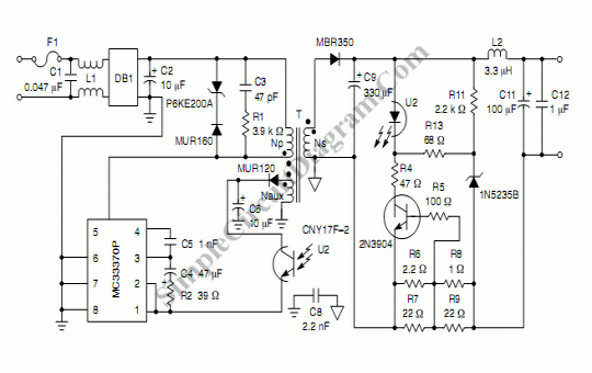
This circuit generates a constant current, constant voltage switched-mode power supply (SMPS). It is designed to efficiently charge a battery using a constant current, constant voltage approach. The circuit operates as a constant current, constant voltage SMPS, which is crucial...
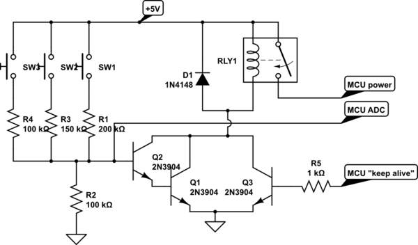
A circuit is being designed that utilizes a combination of switches and resistors to enable a microcontroller to identify which switch has been pressed based on the voltage read, and subsequently perform a switch-specific action. The proposed design incorporates...
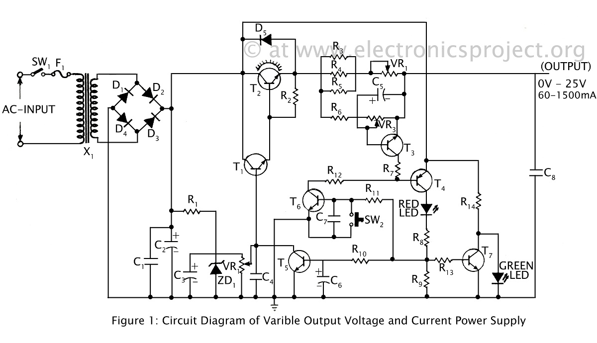
A ripple-free, short-circuit protected variable output voltage and current power supply is presented on this website as a verified project. The circuit diagram includes a description of various power supply circuits. This power supply circuit is designed to provide a...
The current source in the diagram reacts very quickly to changes in the input signal and may be utilized in specific measurements. Differential. The current source depicted in the schematic is designed to provide a stable output current that responds...
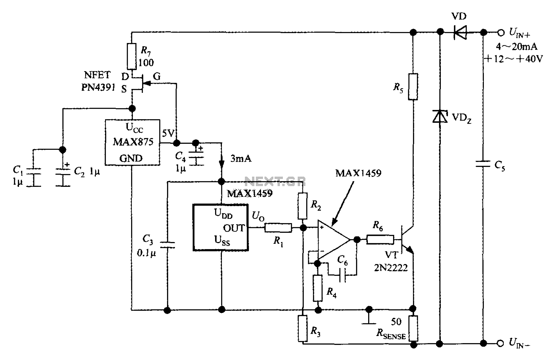
A 4 to 20 mA current transmitter circuit is implemented using the MAX1459, as illustrated in the accompanying figure. The output voltage from the programmable gain amplifier (PGA) is supplied to a spare amplifier chip, and subsequently, an external...