
digital code lock
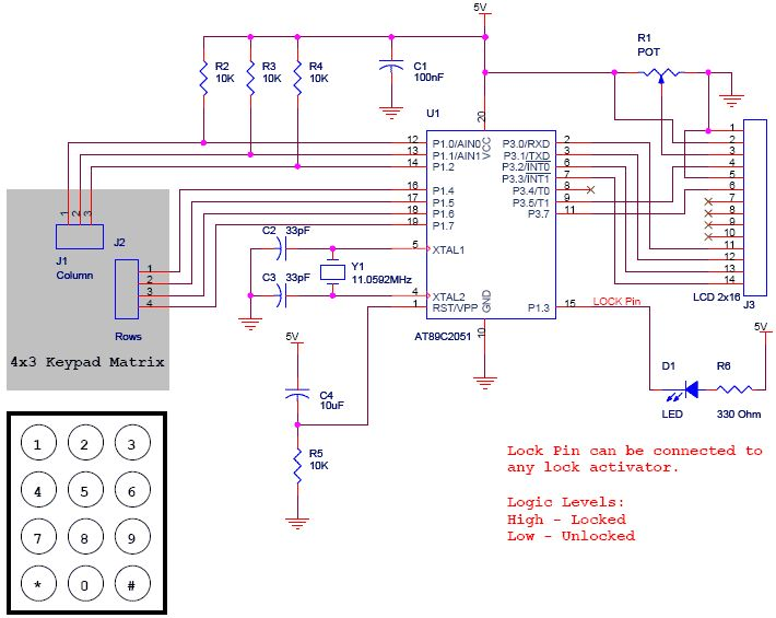
The Digital Code Lock project is structured around the AT89C2051 microcontroller, which acts as the central processing unit. The 4x3 keypad serves as the user interface for code entry, consisting of twelve keys arranged in a grid format, allowing for efficient input of numeric codes. The AT89C2051 microcontroller processes the input from the keypad and manages the logic for both user and master lock functionalities.
The LCD, specifically a 16x2 model, is used to provide visual feedback to the user. It displays prompts for code entry, status messages, and error notifications, enhancing the user experience by informing users of actions taken and required inputs. The output pin connected to an LED serves as a visual indicator of the lock's status, illuminating when the lock is activated and extinguishing when deactivated.
The security of the system is reinforced by the dual lock mechanism: a basic user lock with a 5-digit code and a master lock with a 10-digit code. This hierarchical approach ensures that even if a user forgets their code, access can still be granted through the master code, albeit only by authorized personnel.
To set or change the user code, the system requires the user to input a default sequence (12345) followed by the '#' key, which triggers the controller to request the master password. This additional layer of security ensures that only individuals with the master password can alter the user code, thereby minimizing the risk of unauthorized access.
In summary, the Digital Code Lock project is a well-designed electronic security system that integrates a microcontroller, keypad, LCD, and LED to create a user-friendly and secure locking mechanism. The implementation of both user and master codes, along with the intuitive interface, makes it an effective solution for safeguarding sensitive areas or devices.The project called Digital Code Lock using AT89C2051 ². LCD is used for display and a keyboard is used to input the keys. This project source code is written in C. This a simple project with efficient hacking prevention from Brute Force etc. The basic user lock is of 5 Digits and Master Lock is of 10 digits so its not easy for an intruder to bre ak the lock unless you keep the code simple. The input is taken from a 4G—3 Keypad (please see the schematic for more information) and Display the user input on a 2G—16 LCD. A pin is assigned as output for activating and deactivating the lock. For demonstration an LED is connected to that pin. The user has two options either he/she can use its own 5 digit code or use the default 5 digit code. If user has to do setup his own code, then he has to enter 12345 ³ and press #`. After this. controller will ask for 10 Digit master password which is preprogrammed in the controller. Entering master lock, user can enter the new 5 digit code for the lock and press #` to save it. Keypad has 12 keys (4G—3) starting from 1, 2, 3, 4, 5, 6, 7, 8, 9, *, 0, # (please see the schematic for layout).
Numeric keys are used for entering numbers. *` is used as the Cancel key and #` is used as the Enter key. 🔗 External reference
Related Circuits
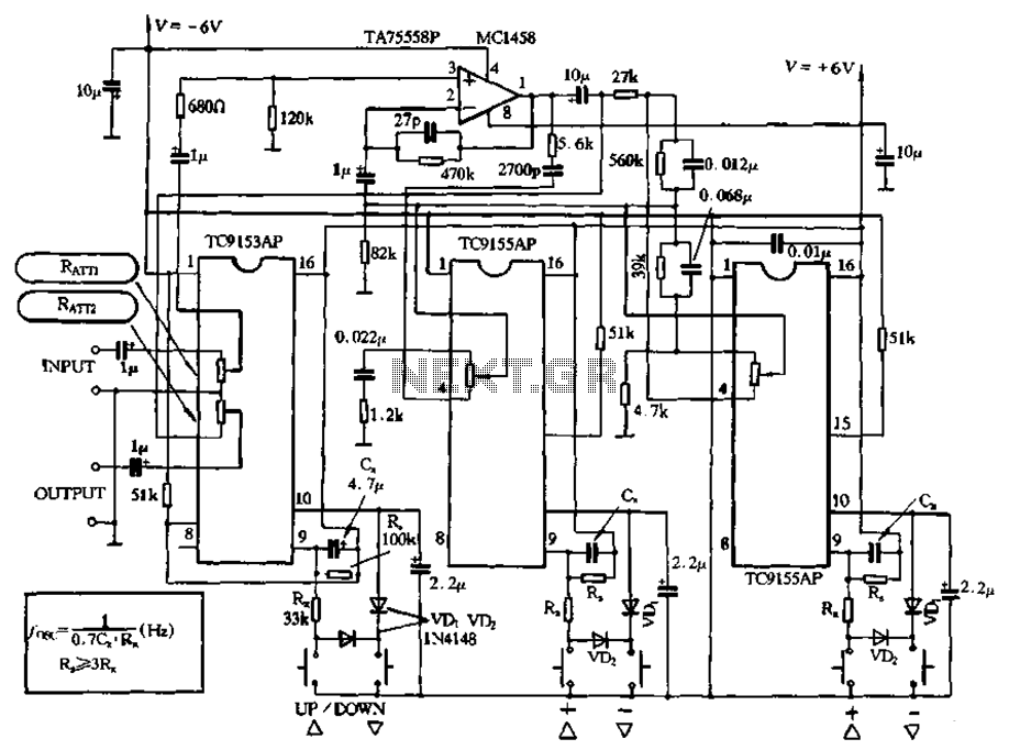
Figure 4-18 illustrates a volume potentiometer T (Xi 153AP) and a tone potentiometer T (155AP) that make up a volume and tone control circuit. This circuit includes Rx and Cx as clock oscillation elements, with values selectable based on...
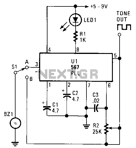
The transducer circuit can function as either a tone encoder or decoder by adjusting the position of switch Sl. The operating frequency of this dual-purpose circuit is set by capacitors C3 and resistor R2. Capacitors C1 and C2 are...
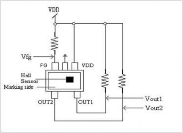
The XC6119 series is a highly precise, low power consumption voltage detector, manufactured using CMOS and laser trimming technologies. The device includes a built-in delay circuit. A release delay time can be set freely by connecting an external delay...
Capacitor C1 is charged through timing resistor R1 when the clock output is high. When C1 reaches the upper threshold voltage, the output signal decreases, and then C1 discharges through R1 until its voltage reaches the lower threshold point....
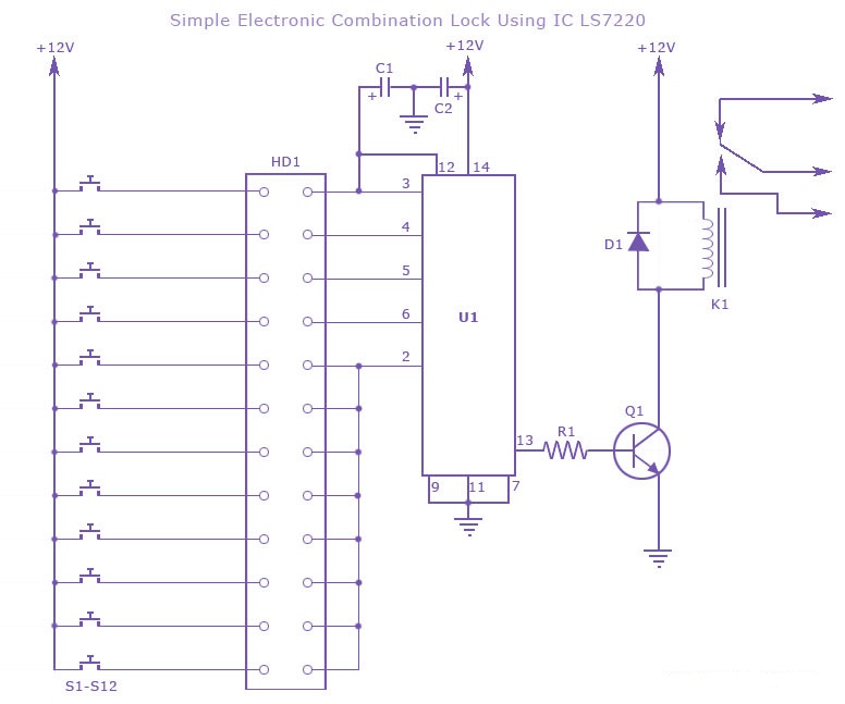
A simple electronic combination lock using the IC LS7220. This circuit employs a relay to control any device when a combination of four digits is entered. Keypads serve as the input method for entering the digits, and the correct...
This is a digital calendar circuit that utilizes a microcontroller to display the date, day, and month on an LED display. The entire system is managed by an 8-bit microcontroller, which operates based on a program embedded in its...