
LED display Digital Calendar AT89C2051

The digital calendar project utilizes an 8-bit microcontroller to manage the display of the current date, day, and month on a series of LEDs. The microcontroller is programmed with firmware stored in its read-only memory (ROM), which dictates the functionality of the calendar system.
The display consists of a total of 50 LEDs: 31 LEDs are designated for the days of the month, corresponding to the maximum number of days in any month; 12 LEDs represent the months of the year; and 7 LEDs indicate the days of the week. Each LED is connected to the microcontroller's output pins, allowing for individual control and activation based on the current date and time.
To ensure continuous operation during power outages, the system is equipped with a battery backup. This feature allows the microcontroller to maintain the current date and time, preventing loss of information when external power is interrupted.
The circuit design includes necessary components such as resistors for current limiting to protect the LEDs, a power supply circuit to manage the input from the battery and external source, and possibly a real-time clock (RTC) module for accurate timekeeping. The microcontroller interfaces with these components through its I/O pins, executing the programmed logic to update the display as needed.
In summary, this digital calendar project exemplifies the integration of microcontroller technology with LED display systems, ensuring reliable performance and user-friendly functionality in a compact design.This Project Digital Calendar using Microcontroller is an advanced digital calendar, which displays the Date, Day, Month over the LED display. It has an 8 bit Microcontroller which runs on the Program embedded on its ROM. Separate LEDs are provided for the date, day, and month. The system has an battery backup so that it can run over all the time even during the power failure. Totally there are 31 LEDs for indicating the date and 12 LEDs for indicating the Month and 7 LEDs to indicate the day. All the above systems are controlled by the Microcontroller. In our project we are using the popular 8 bit micro 🔗 External reference
Related Circuits
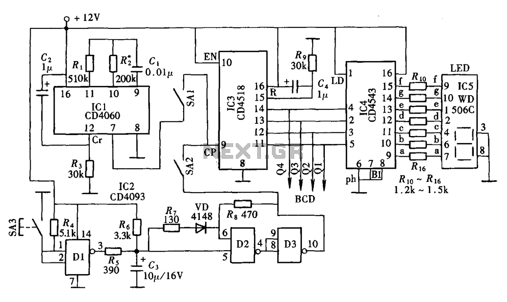
The digital display clock signal source circuit depicted in the figure is derived from a multi-point detection control box within the actual circuit. It primarily comprises an automatic and manual pulse generator, a clock pulse generator, pulse counting elements,...
This is a classic 2-transistor astable multivibrator. Many other NPN small signal or switching transistors can be used, including 2N4401, PN2222, or 2N2222 using the circuit on the left. The circuit can also be inverted using PNP transistors such...
Using only 2 capacitors, 3 resistors, 4 seven-segment displays, 1 xtal, 2 switches n.o. and 1 Microcontroller PIC, you can build this Digital Led Clock. You can use common anode or common cathode display, just select the display type....
The 555 timer IC is connected for Astable Operation, the clock pulses are fed to the 4017 IC via the 10K resistor. The 4017 is a 10 stage counter, therefore the sequence of the traffic lights is spread over...
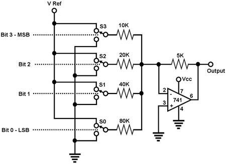
The circuit depicted in Figure 1 is a straightforward 4-bit digital-to-analog converter (DAC). It functions as a simple operational amplifier (op-amp) summer circuit, configured to produce an output voltage that is proportional to the sum of the input voltages....
The basic circuit illuminates up to ten LEDs in sequence, following the rhythm of music or speech picked up by a small microphone. The expanded version can drive up to ten strips, formed by up to five LEDs each,...