
Light Fence Security Alarm Circuit Schematic
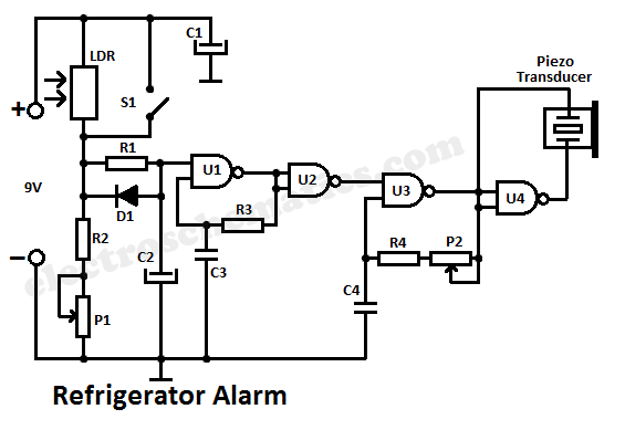
The light fence security beeper circuit employs a phototransistor (T1) that acts as a light sensor, which is critical for detecting interruptions in the light path. The circuit is designed around the 4093 integrated circuit (IC1) configured as a low-frequency astable multivibrator. In its idle state, the circuit remains inactive as long as T1 is conducting, which occurs when it receives light from the green LED (D1). The phototransistor's conduction effectively disables the astable multivibrator, preventing the piezo buzzer from sounding.
When an object obstructs the light beam from D1, T1 stops conducting, which triggers IC1 to produce a low output signal. This transition activates the piezo buzzer, generating an audible alert. The frequency and duration of the beeping sound are influenced by the resistor-capacitor (RC) timing network formed by R3, R4, and C1, allowing for customization of the alarm's characteristics.
The circuit also includes a red LED (D2) that functions as a visual indicator, alerting users to the alarm's status. The design allows for the extension of the effective light path through the use of a reflector and lens assembly, enabling detection over distances of 1 to 2 meters with a high-brightness green LED. Alternatively, a laser pointer can be integrated into the setup, providing a more focused light source for enhanced detection capabilities.
Overall, this light fence security beeper circuit is a versatile and effective solution for various security applications, offering both auditory and visual alerts in response to unauthorized access or movement within a predefined area.A simple light fence security beeper is presented here. This circuit can be used as a door alarm, gate alarm, pathway alarm, etc. Any 12 Volt dc power supply can power the whole circuit. Working of this circuit is straight forward. In standby mode photo transistor T1 receives light from the green LED (D1) and T1 conducts to disable the gated low-frequency astable built around IC1(4093). When this light path is interrupted by any object in the path, T1 stops conducting and IC1 is switched by the low level at its input point (pins 12&13). As a result the piezo-buzzer starts beeping at a slow rate determined by the in circuit values of R3, R4 & C1.
Red LED (D2) is a visual warning indicator. With the help of suitable reflector and lens assembly, length of the light path can be increased. A minimum of 1 to 2 metres is possible with a high-bright green LED as D1. A laser pointer can also be used as the light source. 🔗 External reference
Related Circuits
Operating high-beam headlights while driving on highways can significantly enhance visibility; however, it poses a blinding risk to other drivers. This straightforward circuit can be integrated into the headlight switch to facilitate automatic switching between high and low beam...
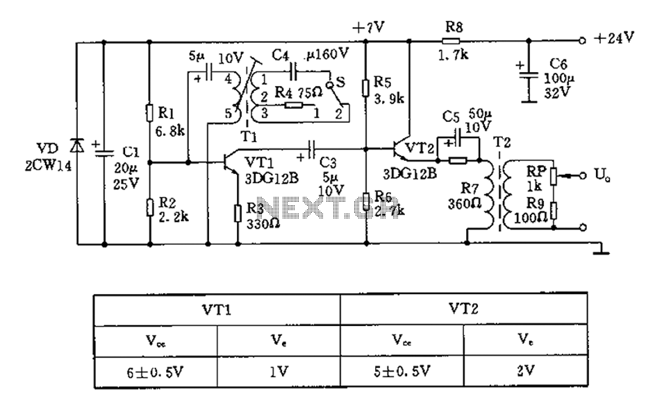
The 450/800Hz oscillation circuit depicted in the figure utilizes transformer coupling. The frequency conversion is achieved by varying the inductance through a variable filter tap (T1). When the switch control signal (S) is set to position 1, the oscillator...
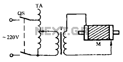
Check the three-phase motor with broken bars as shown in the inspection circuit for the three-phase motor with broken bars. The inspection circuit for a three-phase motor with broken bars is designed to diagnose and evaluate the condition of the...
MOSFETs cannot simply be connected to the drive signal and expected to function correctly. Due to their construction, driving MOSFETs can be complex, particularly for beginners. Many users frequently seek assistance with MOSFET drive issues on various blogs, websites,...
A graphical representation of a system. It often refers to electronic circuits on a printed circuit board or in an integrated circuit (chip). See logic gate and HDL. A graphical representation of a system serves as a crucial tool in...
This simple circuit is based on the well-known integrated circuit LM3915. The main characteristic of this integrated circuit is its ability to manage 10 Light Emitting Diodes (LEDs) in a logarithmic scale, with a 3dB difference between the LEDs,...