
Digital Dice circuit

The digital dice circuit operates by employing a diode matrix that facilitates the conversion of the switch states into a binary representation. Each diode in the matrix, designated as D1 through D9, plays a crucial role in determining the output based on the combination of active switches. The choice of diodes, such as the 1N4148 or 1N914, ensures reliable switching characteristics and minimal forward voltage drop, which is essential for accurate binary conversion.
When the spin switch is deactivated, the circuit interprets the closed or open states of the switches as binary inputs. These binary inputs are fed into the CD4511 decoder driver IC, which is responsible for translating the binary values into corresponding outputs suitable for driving a 7-segment display. The CD4511 is a BCD to 7-segment latch decoder that can effectively handle the binary-coded decimal values, allowing for seamless conversion and display of numbers ranging from 0 to 9.
The 7-segment display is connected to the outputs of the CD4511, which activates the appropriate segments to visually represent the corresponding decimal number. This setup ensures that the circuit can reliably display the results of the dice roll, providing a clear and user-friendly interface. The overall design of the circuit emphasizes simplicity and efficiency, making it an ideal choice for applications requiring a digital representation of random numbers.This dice digital circuit would be a favorite of everyone, by using it to display the numbers. When I turn off the spin switch, it will be converted to a binary input with a diode matrix D1-D9 (1N4148 or number 1N914) and then changed to a 7 segment display with a decoder drive IC No. CD4511 (IC3). 🔗 External reference
Related Circuits
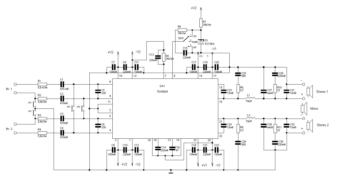
240W power amplifier circuit based on the TDA8924 class D design. This integrated circuit features short-circuit protection at the output, thermal protection, and safeguards against acoustic damage from inrush currents during power on and off. The schematic allows for...
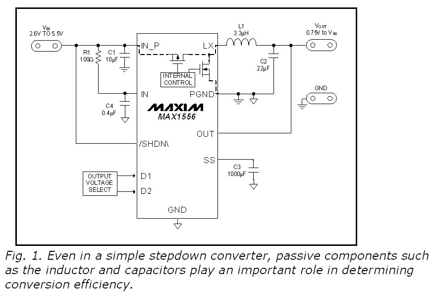
This blog provides insights into SMPS (Switched-Mode Power Supply) circuit diagrams. It offers valuable information for those interested in understanding this topic. Switched-Mode Power Supplies (SMPS) are crucial in modern electronic devices due to their efficiency and compact design. An...
This circuit provides a digital square wave that can be viewed directly or used to drive other circuits. It used the CMOS 4047 Low-Power Monostable/Astable Multivibrator. As used in Tom Duncan's Adventures with Digital Electronics Book, to drive CMOS...
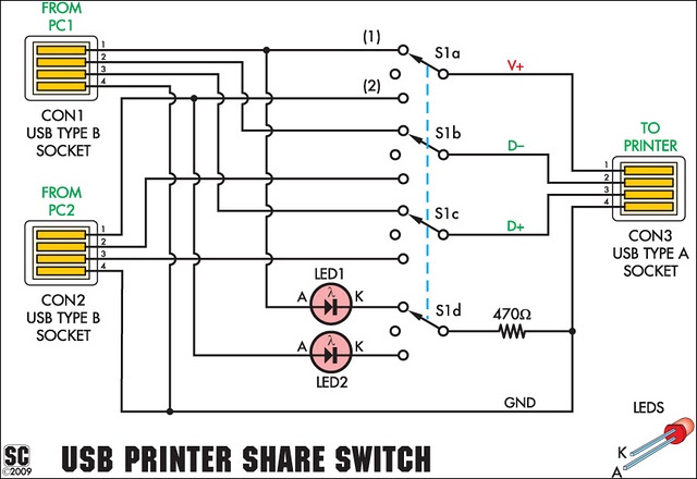
This simple device enables two computers to share a single USB printer or other USB devices, such as an external flash drive, memory card reader, or scanner. A rotary switch is used to select the PC that will be connected...

Battery vampires are circuits designed to extract as much energy as possible from batteries or cells. They are not regulated drivers; rather, they are boost circuits that create a higher output voltage from a low input voltage and provide...
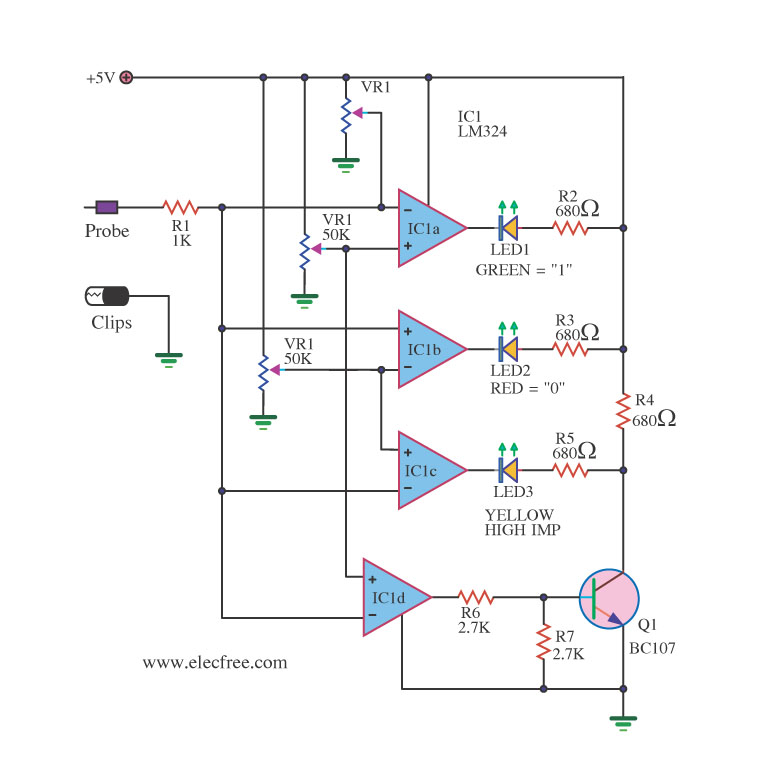
A logic probe is a useful tool for checking digital circuits. It functions similarly to a meter, which is employed to measure power in electrical circuits. A logic probe is an essential diagnostic instrument in digital electronics, designed to analyze...