
Digital Oil-Pressure Gauge
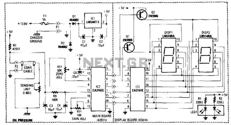
The oil pressure gauge circuit operates by converting the mechanical pressure of the oil into an electrical signal. The sensor, typically a piezoresistive or capacitive type, generates a voltage that correlates with the oil pressure. This voltage is fed to resistor R1, which helps in scaling the signal to a suitable level for further processing.
The dual integrated circuits, IC1 and IC2, are configured to function as a two-digit digital voltmeter (DVM). These ICs convert the analog voltage signal into a digital format, allowing for clear and precise readings of the oil pressure. The multiplexed display is controlled by transistors Q1 and Q2, which select which digit to display at any given time, thus ensuring that the display is efficiently utilized and readable.
Powering the entire circuit, IC1 provides a stable +5 V supply, crucial for the operation of digital components and ensuring accurate readings. Calibration of the gauge is performed using resistor R11, which adjusts the gain of the circuit to match the expected pressure readings. Additionally, resistor R17 is utilized for zero adjustment, allowing the user to set the gauge to read zero when no pressure is applied, ensuring the accuracy of the gauge across its operational range.
Overall, this circuit design exemplifies an effective integration of analog and digital components to provide reliable oil pressure monitoring in automotive and industrial applications. This gauge uses a sensor in conjunction with R1 to develop a dc voltage proportional to oil pressure. IC1 and IC 2 form a two-digit DVM. Q1 and Q2 are display selectors for the multiplexed display. IC1 provides the necessary +5 V to the circuitry. Calibration is via Rll and zero adjust via R17. 🔗 External reference
Related Circuits
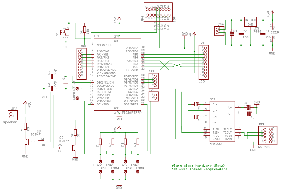
This project outlines a digital clock featuring an alarm function, utilizing a PIC16F877 microcontroller to achieve an accurate 1-second delay with Timer0 through Roman's zero error method. The time is displayed in large font on a 4G—20 character LCD,...
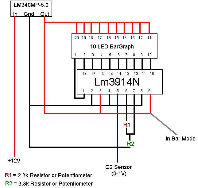
The engine management system monitors its air-fuel ratio using an oxygen sensor (O2) located in the hot exhaust flow, typically positioned before the catalytic converter. All O2 sensors function similarly, with variations including heated sensors or those with multiple...
A sine-wave generator produces a Walsh-function approximation of the sine function. The frequency of the sine wave is determined by a square-wave input to pin 14 of a 7493 integrated circuit. Filter components of the operational amplifier assist in...
The Slave Flash Trigger is activated by pressing a push button. When activated, the indicator lamp emits one to three flickers to indicate the programmed mode. One flicker means the flash will fire with each flash, two flickers indicate...
While driving the car, the gauges turn off and the car stalls immediately. The car will not start until the gauges come back on. When the gauges are off, the car starter will turn over the engine, but it...
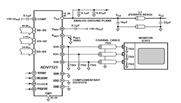
This digital-to-analog converter (DAC) integrated circuit is designed for optimal noise performance, minimizing both radiated and conducted noise. A recommended connection diagram for the ADV7123 is depicted in the following schematic diagram. According to the ADV7123 datasheet, this device...
Warning: include(partials/cookie-banner.php): Failed to open stream: Permission denied in /var/www/html/nextgr/view-circuit.php on line 713
Warning: include(): Failed opening 'partials/cookie-banner.php' for inclusion (include_path='.:/usr/share/php') in /var/www/html/nextgr/view-circuit.php on line 713