5 DOT LED LINEAR LEVEL METER DRIVER
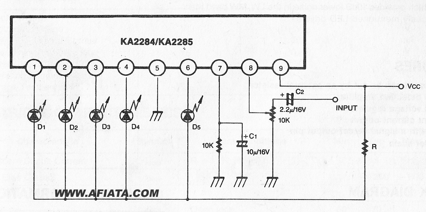
The KA2284 is a monolithic integrated circuit designed for 5-dot LED level meter drives with a built-in rectifying amplifier. It is suitable for both AC and DC level meters, such as VU meters or signal meters.
The KA2284 integrated circuit is a versatile component specifically engineered for driving 5-dot LED level meters. Its monolithic design allows for compact integration, making it an ideal choice for various audio and signal level monitoring applications. The built-in rectifying amplifier enhances its functionality, enabling the KA2284 to process both alternating current (AC) and direct current (DC) signals effectively.
In practical applications, the KA2284 can be utilized in VU meters, which visually represent audio signal levels, as well as in signal meters that measure and display the strength of various signals. The circuit operates by converting the input voltage level into a corresponding LED output, providing a clear and intuitive visual indication of signal strength.
The KA2284 features a straightforward pin configuration that facilitates easy integration into existing designs. It typically includes pins for power supply, ground, input signal, and LED outputs. The internal amplifier is designed to rectify the input signal, allowing the circuit to accurately display both positive and negative signal levels.
When implementing the KA2284 in a circuit, it is essential to consider the supply voltage and ensure that it falls within the specified operating range for optimal performance. Additionally, the choice of LEDs and their arrangement can impact the overall visual output, allowing for customization based on user preferences or specific application requirements.
Overall, the KA2284 is a robust solution for creating effective LED level meters, enhancing both the aesthetic and functional aspects of audio and signal monitoring systems.The KA2284 are a monolithic integrated circuit disigned for 5-dot LED level meter drives with a built-in rectifying a amplifier, it is suitable for AC/DC level meters such as VU meters or signal meters. Disclaimer All files are found using legitimate search engine techniques. This site does not and will not condone hacking into sites to create the links it list. We will and do assume that all links found on the search engines we use are obtained in a legal manner and the webmasters are aware of the links listed on the search engines. If you find a URL that belongs to you, and you did not realize that it was "open to the public", please use the report button to notify the blogmaster of your request to remove it or it will remove within 24 hours.
This is not an invitation for webblog haters to spam with requests to remove content they feel that is objectionable and or unacceptable. Proof of URL ownership is required. NOTICE: This Blog Has Already Been Reviewed And Accepted By Blogger. com 🔗 External reference
Warning: include(partials/cookie-banner.php): Failed to open stream: Permission denied in /var/www/html/nextgr/view-circuit.php on line 713
Warning: include(): Failed opening 'partials/cookie-banner.php' for inclusion (include_path='.:/usr/share/php') in /var/www/html/nextgr/view-circuit.php on line 713
