
Digital Lock Project
The circuit described involves a complex interaction of digital logic components and control mechanisms to manage a motorized locking system. The use of hex inverters allows for the manipulation of signal states, ensuring that the correct logic levels are maintained throughout the operation. The 74193 synchronous counter plays a critical role in counting the button presses, which are interpreted as control signals for the locking mechanism. The one-shot timers introduce precise timing control, allowing for a delay and a timed activation that is essential for ensuring that the locking mechanism operates smoothly and reliably.
The H-bridge configuration with N-channel MOSFETs provides efficient control of the motor, allowing for bidirectional operation. This design is particularly advantageous in applications requiring precise control of motor direction and speed. The integration of the RJ-11 cable for signal transmission highlights the need for reliable communication between the control circuitry and the motor mechanism housed within the Temple of Wisdom Box. Overall, this schematic represents a sophisticated approach to automated locking mechanisms, combining digital logic, timing circuits, and motor control to achieve the desired functionality.EncoderBit1(LOW) is negated with the hex inverter U5A and sent to the 4-input AND gate U3A along with EncoderBit0(HIGH), the above J-K output (HIGH), and a HIGH value from Vcc. -During these 5 seconds, the encoder knob is rotated so both bits are set LOW. Those 2 outputs are inverted with hex inverters U2A and U8A, making the signals HIGH, and one is sent to the Down input pin of the 74193 synchronous 4-bit counter IC while the other is ANDed (U10A) with the output of a second one-shot (U4A). -The falling edge of the 5 second one-shot triggers the second one-shot U4A for 2 seconds. While the first one-shot acted as a delay, this acts as a timer. During those 2 seconds while the output 1Q of U4A is high, the AND gate U10A outputs a HIGH, which sets the ~LOAD pin on the 74193 counter HIGH and effectively activates the counter and prepares it for the next inputs.
-While the one-shot is still outputting HIGH and the counter is active, Button3 is pressed 3 times, sending 3 singlas to the Up pin and setting outputs QA and QB of the counter HIGH (b`0011` = 3). The two HIGH outputs are ANDed by U17A and that output is further ANDed by U6A with the Enter button.
-As seen above, the correct output is actually the one coming from the U17A AND gate. This signal does not change unless the Reset button is pressed and is then ANDed with the changing Enter button signal. This allows the output to be controlled by pressing the Enter button once the lock is `open`, which is necessary for the second part of the lock.
-The output and inverted output of the U6A AND gate, along with a ground singal, is sent over an RJ-11 cable to the Temple of Wisdom Box (wooden Winchester ammo box) which controls a DC motor latch to lock and unlock the lid. -The latch is operated using an H-bridge of 4 N type MOSFET transistors. The H-bridge works by sending a current either one way or the other to rotate the motor CW and CCW. The current is controlled using 4 transistors and 2 signals - each signal affect the corner transistors, biasing, for example, the top left and bottom right transistors to make the current flow from left to right across the motor.
Inverting the signal produces current flow is the opposite direction. The ground signal is mixed with the TEW ground, the inverted signal is set so the motor rotates CW and thus makes the default position of the latch closed. 🔗 External reference
Related Circuits
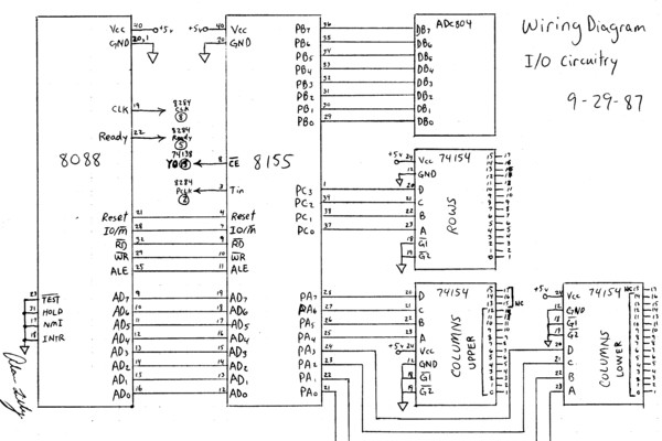
This is an early test program (assembly source code) that was stored on the erasable programmable memory chip (EEPROM). Assembler programming is just one step above programming at the binary level. The described early test program utilizes assembly language, which...
This project outlines the construction of a digital voltmeter utilizing a PIC microcontroller. A character LCD based on the HD44780 is employed to display the measured voltage. The PIC microcontroller used is the PIC16F688, which features 12 I/O pins,...
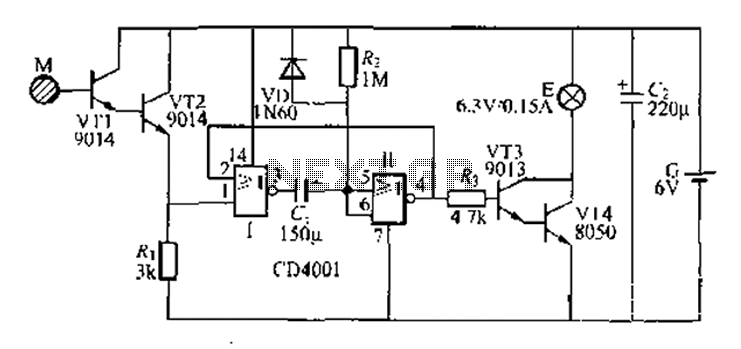
A two-battery powered light touch delay circuit designed for convenience at night. It can be placed on a bed pillow, and when the metal contact M under the capsule is touched, a small lamp will automatically light up. The...
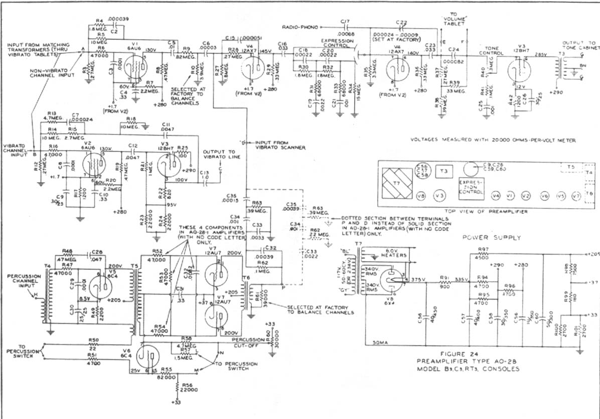
Construct a preamplifier intended to accept a 1/4" keyboard line-level signal and drive a Leslie 147 amplifier. The preamp will utilize a 12AX7 and 12BH7, following the design of a Hammond Organ preamp. The focus will be on the...
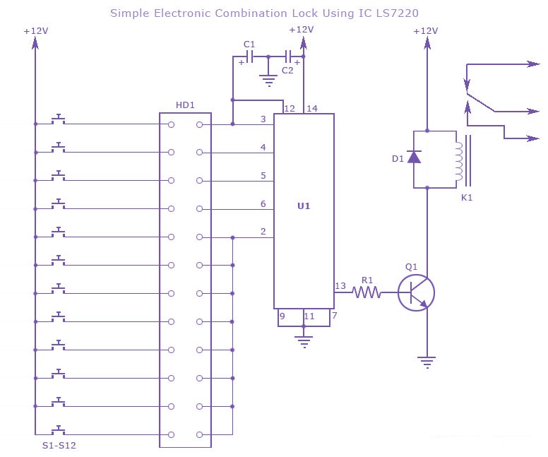
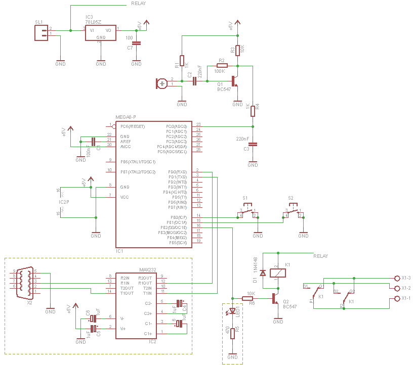
A simple electronic combination lock using the IC LS7220. This circuit employs a relay to control any device when a combination of four digits is entered. Keypads serve as the input method for entering the digits, and the correct...
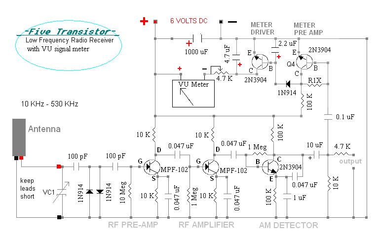
This radio receiver, constructed on a wooden base, utilizes only five transistors to receive longwave beacons and VLF beacons, depending on the connected antenna unit. It incorporates the AMVC-384 capacitor along with one of the "C" antennas. The unit,...