
Digital Remote Thermometer
The digital remote thermometer features a remote sensor that effectively transmits temperature data over the mains supply, allowing for versatile applications in various environments. The operational temperature range of this device spans from 0.0 °C to 99.9 °C, making it suitable for monitoring a wide array of conditions.
The transmitter circuit is composed of several key components. Resistors R1 and R3, each rated at 100K ohms and 1/4 watt, are utilized to set the gain and stability of the circuit. Resistor R2, with a value of 47 ohms and also rated at 1/4 watt, is employed for current limiting purposes, ensuring that the circuit operates within safe parameters. The inclusion of R4, a 5K ohm trimmer resistor rated at 1/2 watt, allows for fine-tuning of the circuit, enabling adjustments to be made for optimal performance.
This design highlights the importance of selecting appropriate resistor values to ensure accurate temperature readings and reliable data transmission. The integration of the remote sensor with the mains supply for data transmission is a notable feature, facilitating ease of installation and reducing the need for additional wiring. Overall, this digital remote thermometer is a practical solution for temperature monitoring in both residential and industrial applications.Digital Remote Thermometer Remote sensor sends data via mains supply Temperature range: 00.0 to 99.9 C Transmitter circuit diagram: Transmitter parts: R1,R3=100K 1/4W ResistorsR2=47R 1/4W ResistorR4=5K 1/2W Trimm.. 🔗 External reference
Related Circuits
The successive approximation Analog to Digital Converter (ADC) is one of the most common types of ADC. It requires few components and is straightforward to operate. Additionally, it always takes the same amount of time to calculate the result....
The Car Voltage Gauge is based on 3 parts. The input circuit is an Analog to Digital Converter (IC2 CA3162E). The purpose of this chip is to sample an analog voltage and convert it to a decimal value which...
The digital lock shown below uses 4 common logic ICs to allow controlling a relay by entering a 4 digit number on a keypad. The first 4 outputs from the CD4017 decade counter (pins 3,2,4,7) are gated together with...
A digital storage oscilloscope (DSO) is a very important piece of test equipment that can do the jobs that a normal CRO just can't handle. Such as capturing single shot and widely spaced waveshapes, and looking at non-repetitive signals...
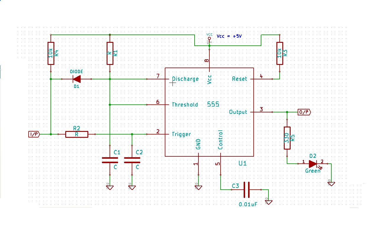
Create a 555 timer-based circuit where the output pin of the 555 timer is held low by default when powered on, and the input pin is held high at power on. The main requirement is that the output pin...
This remote transmits a tone using an infrared LED. This tone is decoded by the receiver. Since the receiver only activates when it detects the tone, there are no accidental activations. The described circuit involves a remote control system that...