
electronic dice schematics
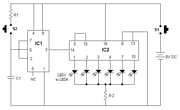
The circuit design consists of a straightforward yet effective setup to simulate a dice roll using LEDs. The IC555 timer is configured in astable mode to produce a continuous square wave output, which serves as the clock input for the CD4017 counter. The frequency of oscillation is determined by the values of R1 and C1; adjusting these components will change the speed at which the LEDs light up, thus altering the randomness of the output.
The CD4017 counter's operation is central to the functionality of the circuit. It sequentially activates its output pins based on the clock pulses received from the IC555. The reset mechanism implemented by connecting pin 5 to pin 15 ensures that the counter only cycles through the first six outputs, effectively limiting the range of the dice to the numbers 1 through 6. This is particularly important for maintaining the integrity of the dice simulation.
The momentary switch S1 initiates the counting process by sending a pulse to the IC555, which in turn generates the clock signal. The output state of the CD4017 is latched when S1 is released, allowing the circuit to display a stable output corresponding to the last activated LED. The randomness of the output is guaranteed by the nature of the clock signal, which produces a new random output each time S1 is pressed.
In summary, this circuit is an elegant solution for simulating a dice roll using basic electronic components. Its design is modular, allowing for easy adjustments and enhancements, such as incorporating additional LEDs or modifying the timing components for different output behaviors.It is good idea to put this circuit in a box and mark/write each LED with number 1 to 6. Now, when switch S1 is pushed momentarily, any one of the 6 LEDs will glow. The Number marked for glowing LED becomes dice`s output. Every time S1 is released, new LED will glow randomly. Chances for each LED to glow is 16. 66%. This circuit makes use of two IC s, IC555 and IC-CD4017. IC-555 is used as square wave generator, and IC(CD4017) as a counter. Actually CD4017 is a divide-by-10 johnson-counter with 10 decoded outputs. IC555 simply generates clock for CD4017, and the clock frequency is controlled by R1 and C1. Counter CD4017 starts counting from 0 to 9 by putting high voltage on each of the 10 pins (one after another). The High voltage shifts from one pin to another on every positive edge of the clock. Since, in our circuit pin-5 is shorted with pin-15(reset), the counter gets reset after reaching 6, and again starts from 0.
Now, when S1 is pushed, IC555 generates clock for CD4017. This clock enables CD4017 to count from 0 to 6 by putting high voltage on each of the 6 pins (one after another). These 6 pins are connected to 6 respective LEDs. When S1 is released, high voltage gets latched to any one of the 6 pins, and this becomes output of the DICE
🔗 External reference
Related Circuits

When the doorbell switch is pressed, two monostable stages are sequentially activated, applying bias to a pair of voltage-controlled resistor stages. These stages modulate the outputs from a pair of tone generators. The resulting signals are then fed to...

This stereo balance indicator circuit diagram is designed using a few common external components. The schematic circuit is simple to build and provides a visual indication with LEDs for left, right, and center balance. Outputs from each channel are...
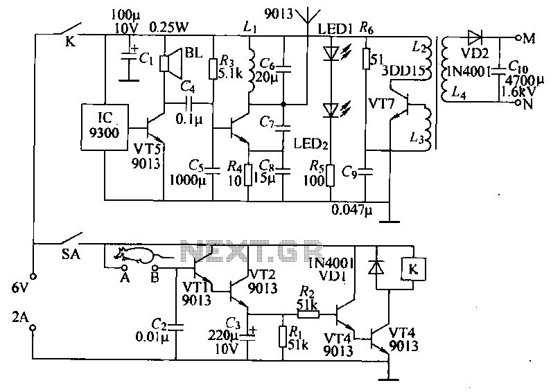
Power-saving electronic mousetrap. This example describes the minimal power consumption, which only occurs when a mouse enters the control zone during foraging activities. After a 30-second delay, the system enters a wait state, making it suitable for outdoor use....

The circuit diagram illustrates a sound, light, and touch-controlled delay self-extinguishing switch. It comprises three main sections: the power circuit, the signal conversion detecting circuit, a delay circuit, and a control circuit. 1. Power Circuit: This section consists of...
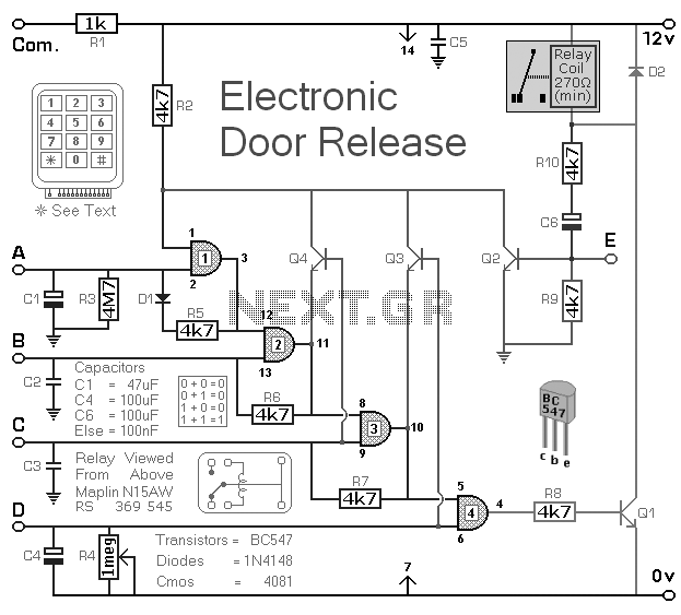
Electronic Door Release Circuit. This circuit is designed to operate an electrical door-release mechanism and can be adapted for other applications. By entering a four-digit code of choice, the relay will energize for a specified period. The electronic door release...
This is an electronic muscle stimulator circuit that stimulates the nerves in the area of the body where electrodes are attached. It is useful for relieving pain. The electronic muscle stimulator circuit operates by delivering electrical impulses through electrodes placed...