
Door circuit text display logic pen 2 CD4011
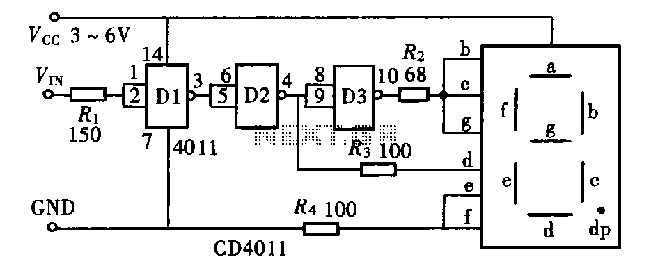
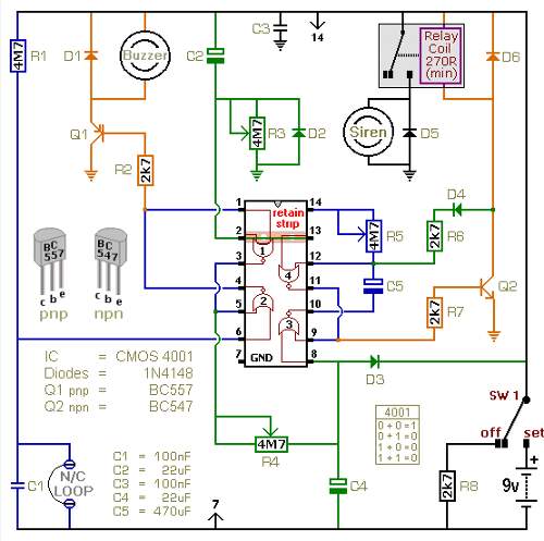
The described circuit employs logic gates to control a text display mechanism, which can serve various applications, including door access systems. The NAND gate, specifically the CD4011, is a quad two-input NAND gate that can be utilized to implement various logical functions. This component is essential in creating the desired logic for the circuit, as it outputs a low signal only when all its inputs are high, making it versatile for constructing complex logic operations.
In conjunction with the NAND gate, the anode LED serves as an indicator or display element. The LED will illuminate based on the output of the NAND gate, providing visual feedback that can indicate the status of the door circuit. The configuration may include resistors to limit the current flowing through the LED, ensuring its longevity and proper functionality.
The circuit can be designed to incorporate additional logic gates, such as NOR gates or inverters, to expand its capabilities. By combining these gates, more complex logical conditions can be established, allowing for a more sophisticated control mechanism for the door or display system. The use of such components enables the development of a robust and reliable electronic circuit that can be tailored to specific operational requirements.
Overall, the integration of the CD4011 NAND gate with an LED in a door circuit logic pen text display exemplifies the application of fundamental digital logic principles in practical electronic design.Door circuit logic pen text display can take many forms, either by the inverters can also be used with non-gates, NOR gates, etc. can also be used. A logical pen as shown by th e NAND gate CD4011 co anode LED composed of.
Related Circuits
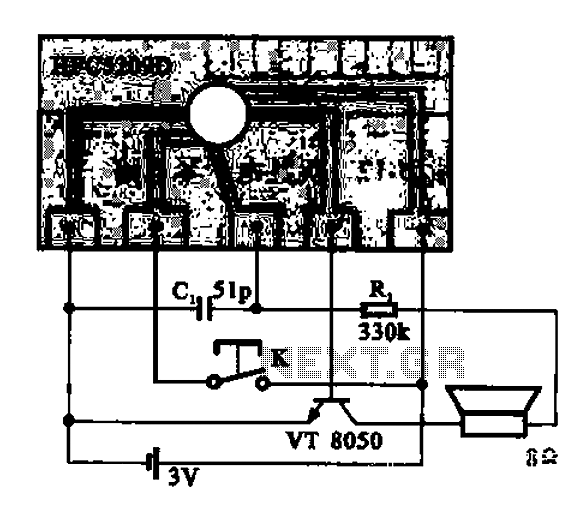
A simple phone automatically displays the recording circuit. In this circuit, after the call, the Ming sound start switch K is activated by the sound of the automatic message HFC5209D. The described circuit functions as an automatic call recording system...
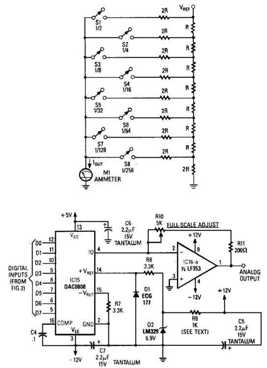
Figure A illustrates an R/2R resistor ladder. Each closed switch increases the current output. A basic channel A/D converter is depicted in Figure B. The voltage reference (D2) is shared among all channels, while the value of the dropping...
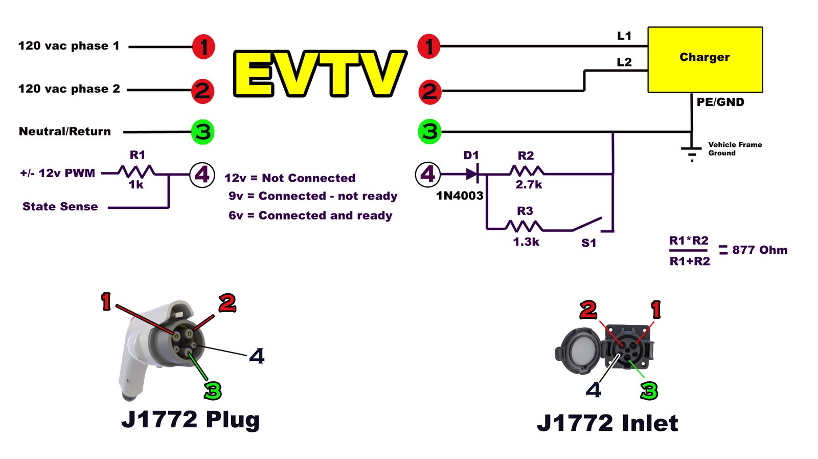
Building battery boxes for the Speedster. Although this topic may not seem thrilling, builders converting vehicles to electric drive often discover that the process of making a car run on battery power is relatively straightforward. However, about 50% of...
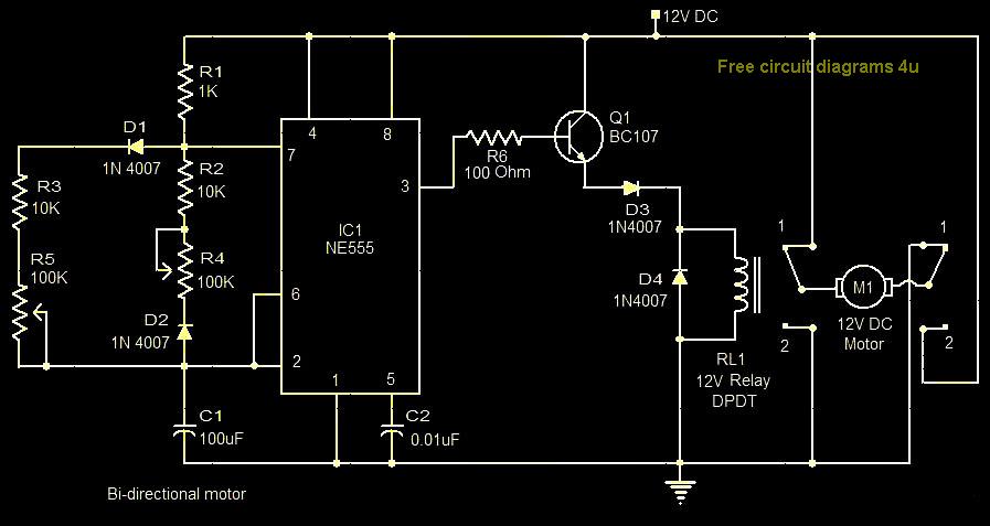
This circuit illustrates a bi-directional motor control circuit utilizing the NE555 integrated circuit (IC). Features include a 12V DC power supply, with the IC employed to control relay RL1. The bi-directional motor control circuit designed with the NE555 IC allows...
The following circuit illustrates a battery-powered burglar alarm sensor circuit. Features include foil tape and passive infrared sensors (PIRs), as well as magnetic reed contacts. This battery-powered burglar alarm sensor circuit is designed to provide an effective security solution for...
Most IR remotes operate effectively within a range of 5 meters. The complexity of the circuit increases when designing the IR transmitter for reliable operation over longer distances, such as 10 meters. To extend the range from 5 meters...