
Digital Stopwatch 0-60sec
The circuit modification described involves the integration of an AND gate into a digital stopwatch circuit originally designed to count from 0 to 99 seconds, allowing it to instead count from 0 to 60 seconds. The BCD (Binary-Coded Decimal) counter plays a crucial role in this transformation as it is responsible for counting the seconds. The fundamental operation of the original circuit involves the BCD counter resetting when the count reaches 100, transitioning from a binary representation of 1001 1001 (which corresponds to 99 in decimal) to 0001 0000 0000 (which corresponds to 0).
To achieve the desired functionality of resetting at 60 seconds, the circuit must be modified to detect the transition from 59 to 60 seconds. This is accomplished by utilizing the outputs Q1 and Q2 of the BCD counter. The output for 59 seconds is represented as 0011 1001 in binary, and the output for 60 seconds is represented as 0100 0000. By connecting the outputs Q1 and Q2 to the inputs of the AND gate, the gate will output a logical high (1) only when both Q1 and Q2 are high, indicating that the count has reached 60 seconds.
When the AND gate outputs a logical high, it activates the RESET (RST) input of the BCD counter. This action forces the counter to reset to zero, effectively restarting the stopwatch. The logical high from the AND gate serves as a control signal that ensures the BCD counter resets precisely at the desired count of 60 seconds, thus transforming the stopwatch's counting range.
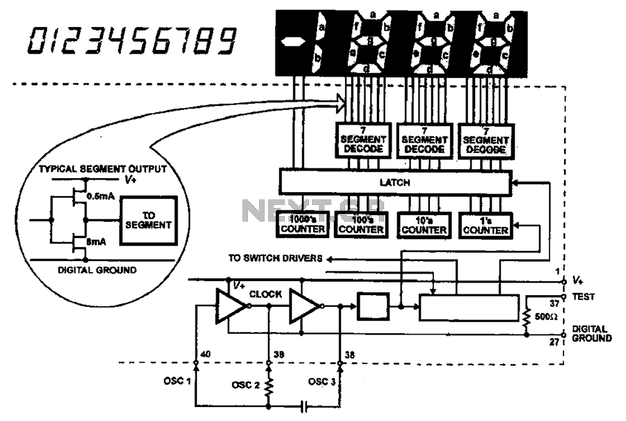
The schematic diagram for this modified circuit would illustrate the BCD counter connected to the AND gate, with the appropriate connections for the RST input. It would also show the connections from the Q1 and Q2 outputs of the BCD counter to the AND gate, demonstrating how the circuit operates to achieve the desired functionality. This modification enhances the stopwatch's utility by limiting its count to a more practical range for timing events that typically last up to one minute.By using the same circuit of the Digital Stopwatch 0-99sec , we can add an AND gate, and transform the 0 ? 99sec stopwatch to a 0 ? 60sec stopwatch. We must find a way to control the RESET function of the BCD counter, which is responsible for the counting of the seconds.
As we studied above, the circuit resets when we have 99 to 100, that is 1001 1001 à 0001 0000 0000. To make a transformation successfully we must force the pulse from 59 to 60 0011 1001 à 0100 0000 on the output of the BCD counter. By placing the AND gate, with its inputs on the Q1 and Q2 of the BCD counter of the decades, we make sure that when the gate closes, the RST input of the BCD counter will be set to logical ?1?, which on its turn, will force the circuit to start over. The transformed circuit appears in picture 2. 🔗 External reference
Related Circuits
This circuit measures the distance covered during a walk. The hardware is housed in a small box that fits into a pocket, and the display operates as follows: the leftmost display, D2 (the most significant digit), shows distances from...
This circuit measures the distance covered during a walk. The hardware is housed in a small box that can be slipped into a pocket. The display is arranged such that the leftmost display, D2 (the most significant digit), shows...
The AC input circuit functions as a converter, transforming an alternating current (AC) signal into a direct current (DC) signal, which is subsequently processed by an analog-to-digital (A/D) converter chip. The input circuit is designed to handle AC signals, typically...
This clock timer uses a PIC16F628 microcontroller to display 3 and 1/2 digit time and control an external load. The clock includes a calendar with leap year and optional daylight savings adjustments. The timer output can be set from...

This circuit provides a visual 9-second delay using a 7-segment digital readout LED. When the switch is closed, the CD4010 up/down counter is preset to 9, and the 555 timer is disabled with the output held high. The circuit utilizes...
This circuit employs switched emitter followers instead of conventional analog switch CMOS chips, resulting in a more effective reduction of crosstalk between channels. It can manage up to 4 Vms with less than -80 dB crosstalk. The circuit design utilizes...