
Digital thermometer with LED / LCD display
The circuit design of the homemade digital thermometer with ICL7106 involves several key components and configurations that ensure accurate temperature measurement and display. The silicon transistor, acting as the temperature sensor, is central to the operation, converting temperature variations into corresponding voltage changes. The voltage drop across the transistor is directly proportional to the temperature, which is critical for the thermometer's functionality.
The choice of power supply is flexible, allowing for either a 9V battery or an external power source, which enhances the versatility of the device. The oscillator circuit, consisting of R1 and C1, is fundamental in determining the sampling rate of the temperature measurements. The frequency of 3 Hz, established by the selected resistor and capacitor values, ensures that the thermometer provides timely updates of the temperature reading.
The display technology varies between the two versions, with the LED display being more power-intensive and requiring a stabilized power supply, whereas the LCD version benefits from lower power consumption and simpler power requirements. The use of a superbright display in the ICL7106 version allows for clear visibility while maintaining low current draw, making it ideal for portable applications.
Calibration is a critical aspect of the thermometer's design, ensuring that the readings are accurate across the specified temperature range. The two-step calibration process using trimmers allows for fine-tuning of the device, accommodating variations in the temperature sensor's characteristics and ensuring reliable performance.
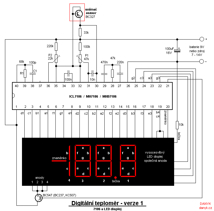
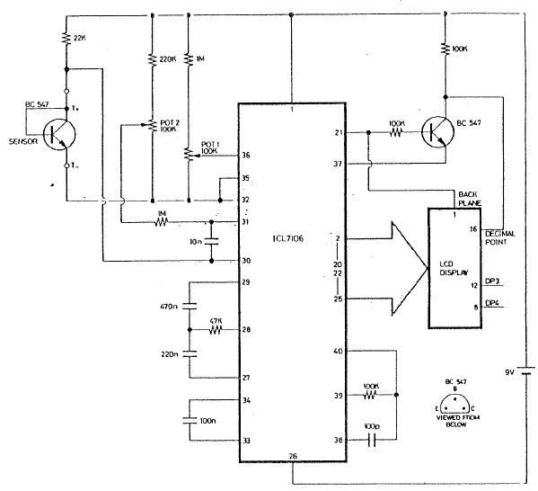
In summary, this homemade digital thermometer design effectively combines simplicity with functionality, providing an accessible means for temperature measurement that can be adapted for various applications, including room temperature monitoring and other uses where accurate temperature readings are essential.Now we bring you two versions of a homemade digital thermometer with ICL7106 that I recently built. One version uses a LED display, the second version LCD display. In both versions, is used silicon transistor as a temperature sensor. The temperature is determined by the voltage drop, temperature dependence is approximately -2. 2 mV / °C. Power can be either a 9V battery or a suitable power supply. Oscillator with R1 and C1 determines the sampling frequency - using 100k and 100p the frequency is 3 Hz. Theoretical temperature range is from -199. 9 to 199. 9 °C, the real temperature range is limited by the measuring transistor to approximately -65. 0 To 150. 0 °C. Resolution to 0. 1 °C. If you want to use it as a room thermometer, it is not necessary to use the hundreds digit, (left) or minus sign.
Also digit right from the decimal point may be omitted if 1 °C resolution is sufficient. A simple room thermometer thus requires only two-digit display, as on photo below. LED version is usually constructed with the circuit ICL7107, which has a higher output current, but this circuit requires symmetrical stabilized power supply. Advantage of 7106 is a simple power supply without stabilization. The problem is solved by a low curren (1 mA) superbright display. 7106 is also easier to salvage from something (like digital multimetr) than 7107. I will not discuss the 7107 here. Info on both those integrated circuits can be found in their datasheet. Here, the circuit 7106 is connected in the usual way. LCD is driven by AC 60Hz signal. At all outputs for display and the common electrode terminal have a rectangle 60Hz waveform. Outputs for the segments that are not to be displayed, have a voltage in phase with a common electrode.
Outputs for segments that are displayed, are out of phase. T1 is used as an inverter for the decimal point. Thermometer with LCD is also possible to make by rebuilding cheap or old digital multimeter (most of them used circuit ICL7106 or some equivalent. 7106). Current consumption is less than 1 mA, therefore it is suitable for battery power. The thermometer must be calibrated. Calibration is performed using the trimmer P1 and P2 in two steps. The first step is to set the zero using crushed ice (the ice and water mix). Set P2 approximately in the center. Probe (Transistor) Place in a waterproof container and dip into crushed ice (ice pieces in water). After stabilizing the set P1 and to display 00. 0 °C. In the second step P2 is set according to a known temperature, preferably in boiling water at 100 °C.
Alternatively the P2 setting can be made according to another thermometer at room temperature. For accurate setting you can use multiturn trimmers. Various thermometers. To calibrate P2 they also can be used (to avoid working with boiling water) but the accuracy is worse. Mercury laboratory thermometers are fairly accurate, cheap digital thermometers from Vietnamese still usefull, alcohol thermometers are inaccurate (deviation commonly about 1 °C).
🔗 External reference
Related Circuits
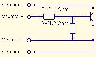
This is a straightforward guide to constructing a digital switch for a camera, enabling photo capture through microcontrollers. Required components include: 1. A digital switch for a camera can be implemented using a microcontroller, such as an Arduino or...
INTRODUCTION It is essential to monitor the operation of nearly all automated and semi-automated devices, such as washing machines and autonomous systems. Monitoring the functionality of automated and semi-automated devices is crucial for ensuring optimal performance and reliability. This can...
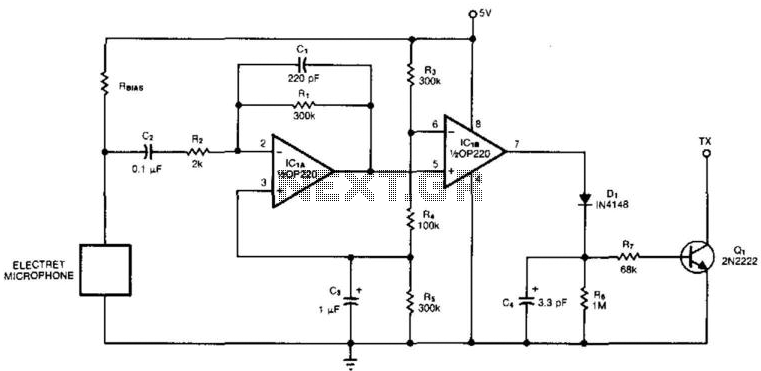
An electret microphone feeds a bandpass filter circuit (IC1A), which subsequently drives a comparator. This comparator activates Q1, a switch that conducts when audio signals from IC1B cause D1, C4, R6, and R7 to bias it ON. The circuit begins...
This circuit is a small digital roulette. It consists of an oscillator IC1, a counter IC2, and transistors Q1-7 that drive the common cathode display DSP1. The power supply typically comes from a 9V battery, but it can also...
The input mentions the 89S51/52 microcontrollers, but the accompanying image shows the 89C51. Clarification is needed regarding which microcontroller should be used with the provided .hex file without requiring changes to the file. The 89S51 and 89S52 are part of...
The ICL7106 integrated circuit contains all the active circuitry for a 3 1/2 digit panel meter (DPM) in a single chip. It was designed to interface directly with a liquid crystal display (LCD). The potential difference across a silicon...
Warning: include(partials/cookie-banner.php): Failed to open stream: Permission denied in /var/www/html/nextgr/view-circuit.php on line 713
Warning: include(): Failed opening 'partials/cookie-banner.php' for inclusion (include_path='.:/usr/share/php') in /var/www/html/nextgr/view-circuit.php on line 713