
Digital Voltmeter circuit

The ICL7107 is designed to convert analog signals into digital representations with a resolution of 3 1/2 digits, allowing for a maximum display reading of 1999. This device is particularly useful in applications requiring precise measurements, such as multimeters and other measurement instruments.
The internal voltage reference ensures stable and accurate conversions by providing a consistent reference voltage for the A/D conversion process. High-isolation analog switches are incorporated to minimize signal interference and maintain the integrity of the input signal during conversion.
The sequential control logic orchestrates the operation of the device, managing the timing and sequence of the conversion process to ensure accurate readings. The display drivers are responsible for controlling the LED display, allowing users to easily read the output values.
In terms of pin configuration, the ICL7107 typically includes pins for the analog input, reference voltage input, and control signals. The analog input is where the signal to be converted is applied, while the reference voltage input connects to the internal voltage reference or an external reference voltage source. Control pins manage the operation of the device, including enabling the display and starting the conversion process.
Overall, the ICL7107 is a versatile and reliable A/D converter well-suited for a variety of electronic measurement applications, providing accurate digital output from analog signals with ease of integration into existing circuits.The ICL7107 is a 3 1/2 digit LED A/D convertor. It contains an internal voltage reference, high isolation analog switches, sequential control logic, and the display drivers.. 🔗 External reference
Related Circuits
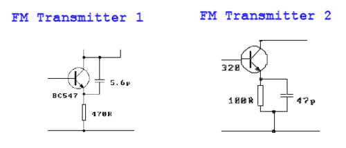
These two tank circuits appear to broaden the operating spectrum. The accompanying information sheet indicates that when both circuit stages oscillate at the same frequency, the power output reaches its maximum. This suggests that if the tunable tank circuit...
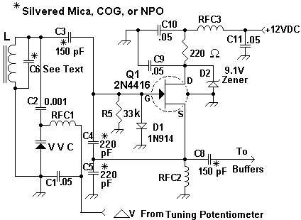
Figure 1 illustrates the VFO oscillator circuit operating within the frequency range of 10.58 to 10.74 MHz. This circuit is a redesigned version of a previously presented Colpitts oscillator, with a clearer representation. The inductor, labeled "L," has an...
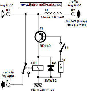
In many countries, it is now mandatory or at least recommended to have a rear fog light on a trailer, with the additional requirement that when the trailer is attached to the vehicle, the rear fog light of the...
A device that conducts electric current and converts electrical energy into another form. Power consumed by a device or circuit while performing its function can be represented by a resistor and capacitor. The capacitor in the load circuit represents...
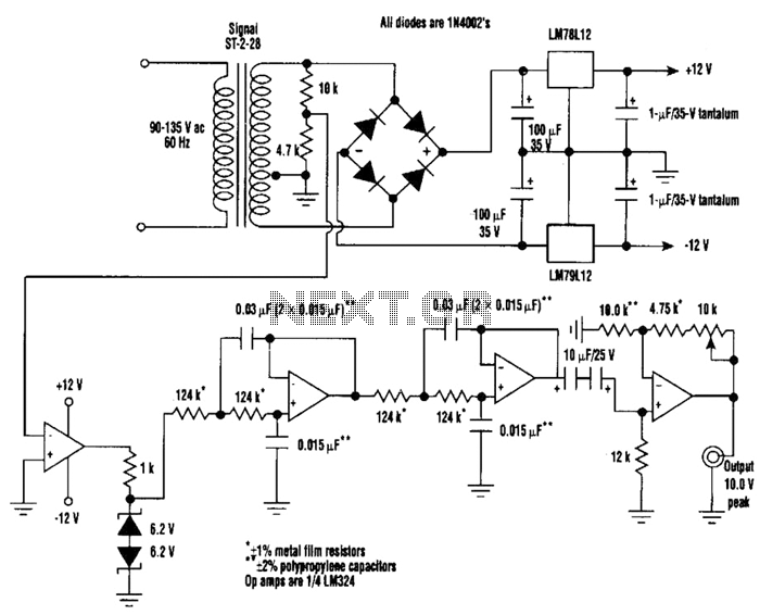
A highly stable 60-Hz sine wave can be delivered with this circuit, which offers a different and much simpler approach to achieving a stable amplitude. Capacitor coupling in the last stage removes any DC component caused by unequal Zener...
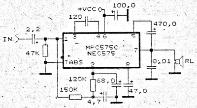
An amplifier circuit is particularly well-suited for use in confined spaces, such as within vehicles. It requires a voltage supply ranging from 9 Volts to a maximum of 17 Volts. This amplifier circuit utilizes the IC MPC575C, which is...