
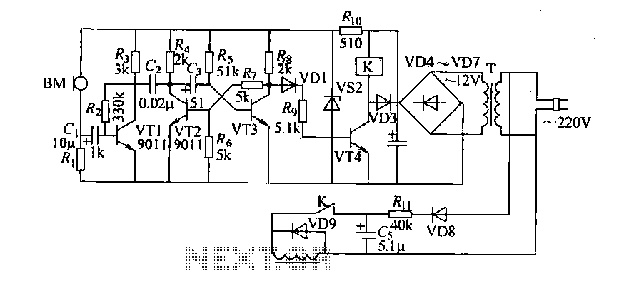
Servo Motor Controller Circuit

The servo motor controller circuit employs the CMOS IC 7555 configured in astable mode to produce a continuous square wave output. This output serves as a pulse signal that is crucial for controlling the position and movement of the servo motor. The frequency and duty cycle of the generated pulses can be adjusted by changing the resistor and capacitor values connected to the 7555 IC.
In astable mode, the 7555 operates without any stable state, constantly switching between high and low outputs. The timing components, typically a combination of resistors (R1, R2) and a capacitor (C), define the frequency (f) of the output waveform. The frequency can be calculated using the formula:
\[ f = \frac{1.44}{(R1 + 2R2) \cdot C} \]
The duty cycle, which determines the proportion of time the output is high versus low, is influenced by the resistor values, allowing for fine-tuning of the pulse width. This is critical for matching the requirements of the specific servo motor being controlled.
The output of the 7555 is connected to the control input of the servo motor, which interprets the pulse width to adjust its position accordingly. Additionally, the circuit may include a power supply section to provide the necessary voltage levels for the IC and the servo motor, ensuring reliable operation.
Overall, this simple servo motor controller design is effective for applications requiring precise control of motor position, such as in robotics, automation systems, and remote-controlled devices.This is the simple basic design of servo motor controller with pulse generator. It uses the CMOS IC 7555 in the Astable mode to generate pulses to drive th.. 🔗 External reference
Related Circuits
Cook in advance to open the door with a coal stove; before using the fire, it should be strong. This is an automatic door opening device that can automatically open the door before the regular homeowner, eliminating the need...
The series of decibel meters functions to determine the signal strength level delivered to the speakers in an audio system. This decibel meter circuit is commonly referred to as VU meters in high-fidelity audio systems. The series of decibel...
The frequency jammer operates by generating interfering RF noise centered around a 2.45 GHz carrier frequency. As the power of this noise increases, the signal-to-noise ratio of the wireless communication channel decreases, leading to a higher bit error rate...
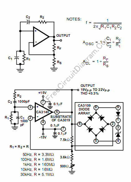
The high input impedance, high slew rate, and high voltage characteristics of the CA3140 operational amplifier make it suitable for use in a Wien-bridge sine wave oscillator. The basic circuit configuration for the Wien-bridge sine wave oscillator is depicted...
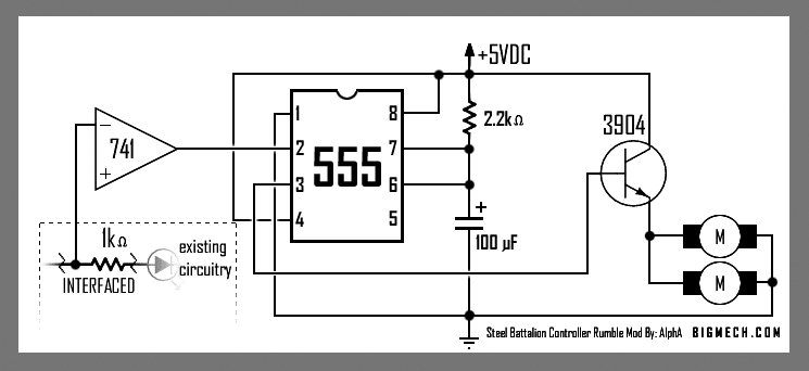
This is the large controller utilized for the game Steel Battalion for the Xbox. The schematic diagram was sourced from an individual named Alpha who created it for his own use. The Steel Battalion controller is a specialized input device...

The following circuit illustrates an Automatic Loudness Control Circuit Schematic. This circuit is based on the TL072 integrated circuit. Features include various functionalities. The Automatic Loudness Control Circuit is designed to adjust audio signal levels dynamically, enhancing the listening experience...
Warning: include(partials/cookie-banner.php): Failed to open stream: Permission denied in /var/www/html/nextgr/view-circuit.php on line 713
Warning: include(): Failed opening 'partials/cookie-banner.php' for inclusion (include_path='.:/usr/share/php') in /var/www/html/nextgr/view-circuit.php on line 713