
Digital Voltmeter with ICL7129ACPL A/D converter
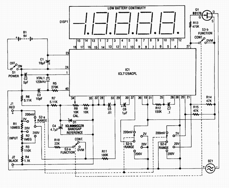
The circuit utilizes the Maxim ICL7129ACPL, a highly integrated analog-to-digital converter (ADC) that supports a 4 1/2-digit display. This ADC is designed specifically for digital voltmeter applications, offering high accuracy and low noise. The device operates by converting the analog input voltage into a digital representation, which is then displayed on an LCD. The ICL7129ACPL features a dual-slope integration method, which enhances noise rejection and allows for stable readings, especially in environments with fluctuating electrical noise.
For voltage reference stability, the circuit employs the ICL8069 CCZR 1.2-V band-gap reference diode. This component provides a stable reference voltage necessary for accurate ADC operation. The band-gap reference ensures that the voltage remains consistent across varying temperatures and supply voltages, which is crucial for maintaining measurement precision.
The range selection is facilitated by a multi-position switch (S2a-b-c), allowing users to select between four voltage ranges, with a maximum input voltage capability of 200 V. This feature enables the circuit to measure a wide variety of voltage levels, making it versatile for different applications.
Continuity testing is integrated into the design, indicated by the inclusion of a piezoelectric buzzer. The buzzer activates when the circuit detects continuity, providing an audible signal to the user, which is particularly useful in troubleshooting and ensuring proper connections in electrical systems.
The circuit includes another switch (S3) that allows the user to toggle between digital voltmeter (DVM) mode and continuity testing mode. This dual functionality enhances the utility of the device, making it suitable for both voltage measurements and basic continuity checks.
The frequency of the crystal oscillator (Crystal 1) is a critical component in this design. It typically operates at 120 kHz to optimize 60 Hz noise rejection. However, the circuit design allows for the crystal frequency to be changed to 100 kHz if the application demands maximum rejection of 50 Hz interference. This adaptability ensures that the device can be tailored for specific environments where different types of electrical noise may be present.
In summary, this circuit provides a comprehensive solution for high-precision voltage measurement and continuity testing, leveraging advanced components and design techniques to deliver reliable performance in various applications.This 4 1/2-digit DVM circuit is built around a Maxim ICL7129ACPL A/D converter and LCD driver. An ICL8069 CCZR 1.2-V band-gap reference diode is used for a voltage reference. S2a-b-c select one of four ranges up to 200 V (maximum). The meter also has a piezoelectric buzzer for continuity testing. S3 selects either DVM or continuity. Crystal 1 can be changed to 100 kHz if maximum rejection of 50 Hz is desired. The crystal normally provides 120 kHz for best 60-Hz rejection. This is caused by the dual-slope conversion technique used in IC1. 🔗 External reference
Related Circuits
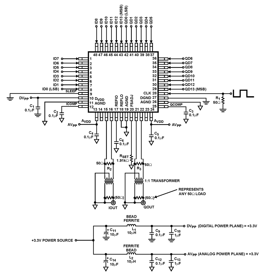
The ISL5929 is a dual 14-bit, 130/210+ MSPS (Mega Samples Per Second), CMOS, high-speed, low-power, digital-to-analog converter (DAC) designed specifically for high-performance communication systems, such as base transceiver stations utilizing 2.5G or 3G cellular protocols. The ISL5929 DAC is engineered...
Warning: Missing argument 2 for wpdb::prepare(), called in /home3/nithish/public_html/btechzone.com/wp-content/plugins/sharebar/sharebar.php on line 112 and defined in /home3/nithish/public_html/btechzone.com/wp-includes/wp-db.php on line 992 Warning: Missing argument 2 for wpdb::prepare(), called in /home3/nithish/public_html/btechzone.com/wp-content/plugins/sharebar/sharebar.php on line 124 and defined in /home3/nithish/public_html/btechzone.com/wp-includes/wp-db.php on line 992 This...
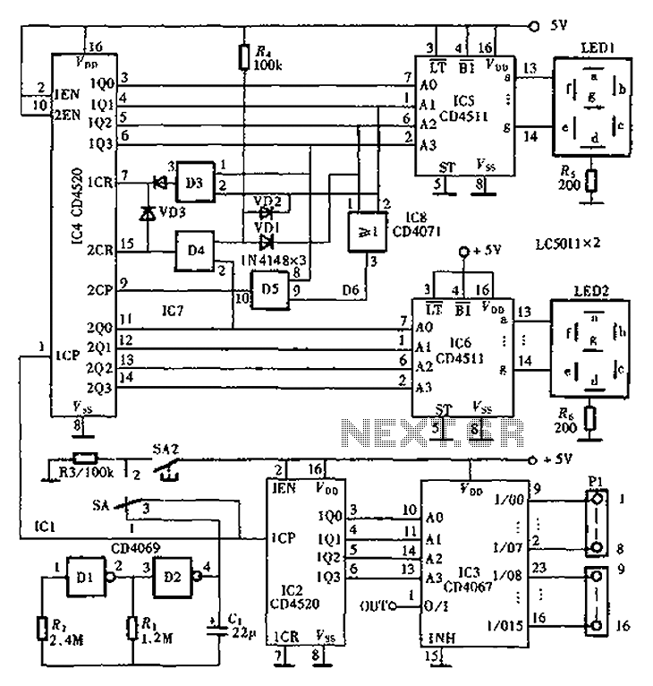
An automatic inspection circuit designed for the simultaneous detection and control of multiple production equipment. This inspection circuit can perform sixteen regular inspections of production equipment. It consists of a pulse generator, multiple inspection circuits, and an automatic inspection...
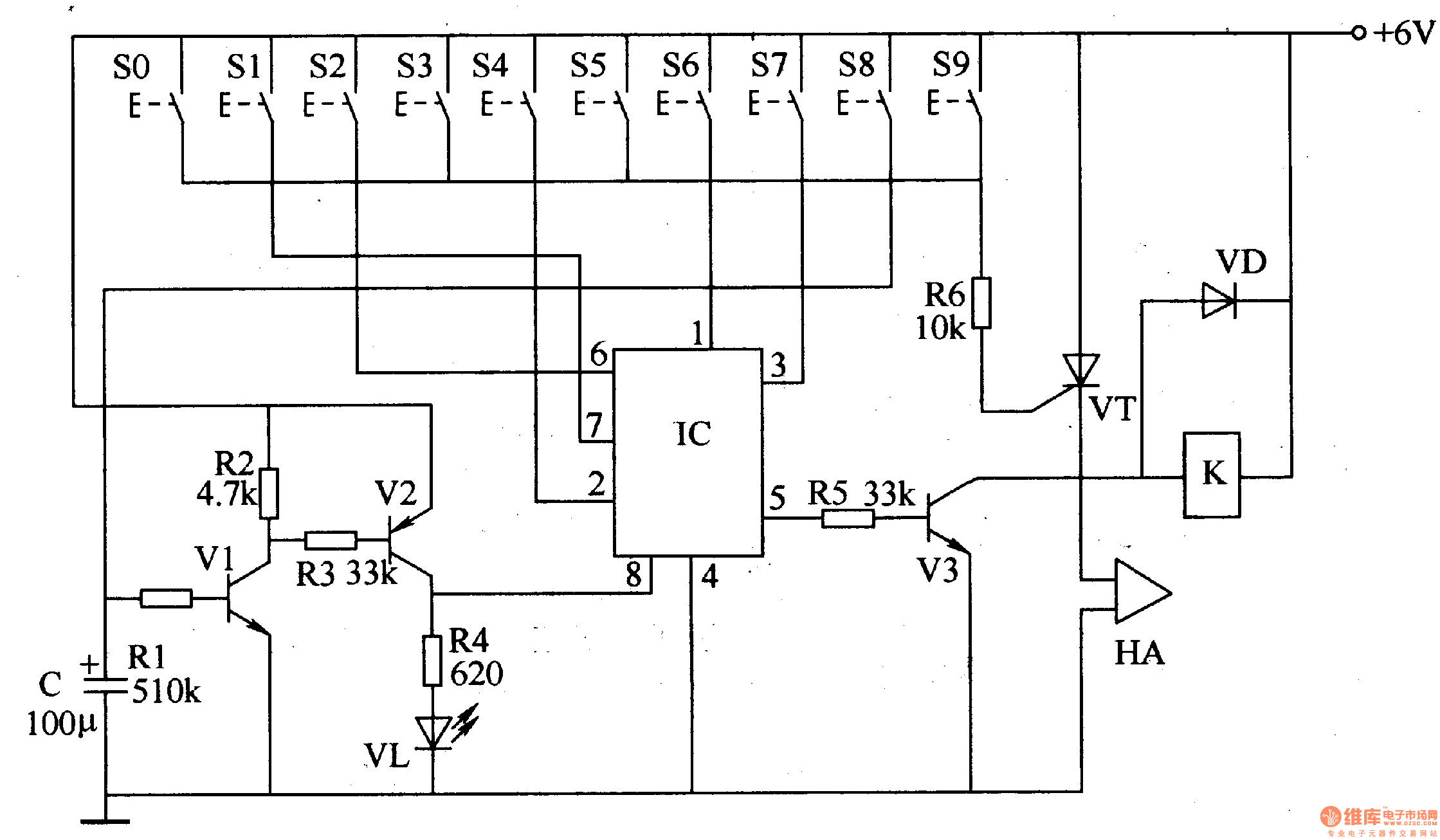
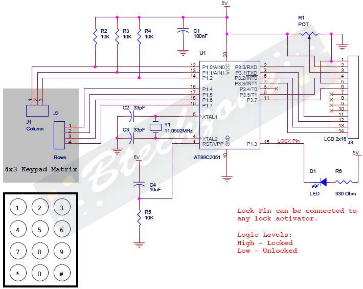
The digital lock circuit consists of a timing trigger circuit, a trick lock circuit, a sound and alarm circuit, and a control implementation circuit, as illustrated in Figure 3-101. The timing trigger circuit is made up of transistors V1...
This is a low-power voltmeter circuit suitable for alternative energy systems operating on 12-volt and 24-volt batteries. The voltmeter features an expanded scale design, allowing it to display small voltage increments within the 10 to 16-volt range for 12-volt...
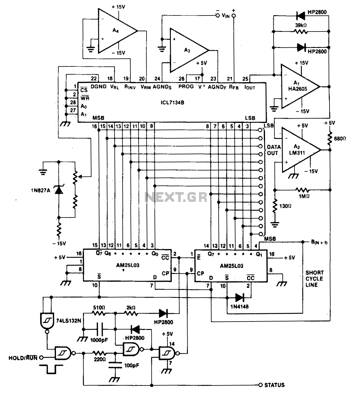
A bipolar input, high-speed A/D converter utilizes two AM25L03 devices to create a 14-bit successive approximation register. The comparator consists of a two-stage circuit featuring an HA2605 front-end amplifier, which is employed to minimize settling time issues at the...
Warning: include(partials/cookie-banner.php): Failed to open stream: Permission denied in /var/www/html/nextgr/view-circuit.php on line 713
Warning: include(): Failed opening 'partials/cookie-banner.php' for inclusion (include_path='.:/usr/share/php') in /var/www/html/nextgr/view-circuit.php on line 713