
Automotive electronic password lock circuit diagram
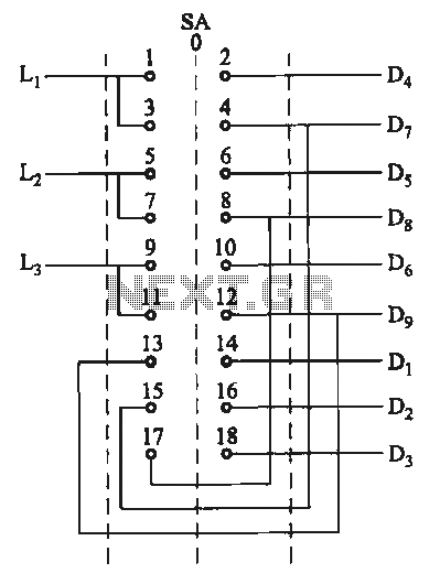
The automotive electronic code lock circuit utilizes an integrated circuit (IC) 5G058, which serves as the core controller for the locking mechanism. The circuit is designed to enhance vehicle security by requiring a specific sequence of key presses to unlock the system. The six valid input keys, labeled S1 through S6, must be pressed in the correct order to successfully disengage the lock. This sequential requirement helps to prevent unauthorized access, as random key presses will not unlock the system.
The external key switch connects to the power supply, providing the necessary voltage for the circuit to operate. Each key input is monitored by the IC, which processes the sequence and determines whether the input is valid. If the correct sequence is followed, the IC will activate the unlocking mechanism, allowing access to the vehicle.
In addition, the circuit includes a button switch, denoted as S7, which is connected to a false key input. This feature serves as a deterrent against tampering. If an incorrect key is pressed, the circuit can trigger an alarm or other security measures, alerting the owner to potential unauthorized attempts to access the vehicle.
Overall, the automotive electronic code lock circuit is a sophisticated security solution that combines ease of use with robust protection against theft. The design emphasizes reliability and user-friendliness, making it an effective choice for modern automotive applications.Automotive electronic code lock circuit is shown as above. ICl is exclusive lock for the integrated circuit 5G058, its ? ~ ? feet connect external key switch to the power supply. They are six valid input keys. The unlock must follow the sequence of Sl ~ S6; pin ? button switch S7 is connected to the false key input. It is free to pick one or a few keys on.. 🔗 External reference
Related Circuits

This schematic represents a radio receiver circuit based on the TDA7088T, which is suitable for use in mono portable and pocket radios. The TDA7088T is a bipolar integrated circuit designed to operate with a minimal number of peripheral components...
A typical circuit for welding equipment is illustrated in the following circuit diagram. The turn-on delay can be accurately controlled with Potentiometer P2, allowing for effective discharge management. The welding equipment circuit typically incorporates several key components to ensure proper...
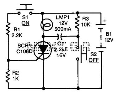
After the SCR is activated, capacitor CI charges up to nearly the full supply voltage through resistor R3 and the anode of the SCR. When switch S2 is later closed, it grounds the positive terminal of CI, causing the...
A high voltage power supply DC converter that operates between 3V to 500V has been suggested for use with Geiger tubes. However, during simulation, the output remained at nearly 9V, which matches the input voltage. The schematic drawn has...
The motor switch control circuit depicted in the figure provides two speed settings for counter-steering, allowing for operation at two speeds in opposite directions. The motor switch control circuit is designed to facilitate the operation of a motor at two...
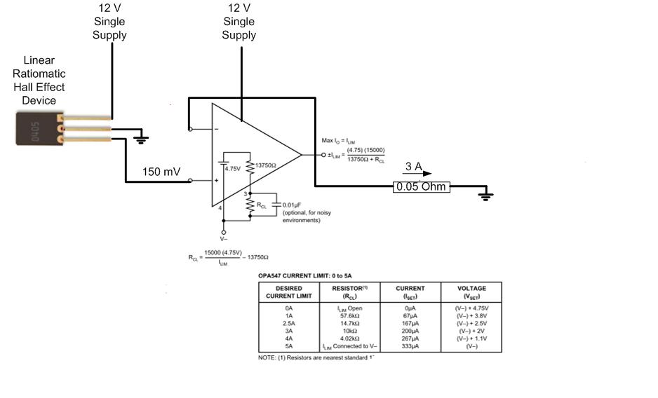
The proposed approach would dissipate (12V)(3A) = 36 watts, which results in significant heat generation in the circuit. This necessitates consideration of two alternatives: 1) Operating the op-amp at a lower supply voltage, if feasible, or 2) Utilizing a...
Warning: include(partials/cookie-banner.php): Failed to open stream: Permission denied in /var/www/html/nextgr/view-circuit.php on line 713
Warning: include(): Failed opening 'partials/cookie-banner.php' for inclusion (include_path='.:/usr/share/php') in /var/www/html/nextgr/view-circuit.php on line 713