
Direct Box (instant music recording instrument for Musicians)

Signal recording devices are categorized into two types: active and passive. A passive device consists of a symmetrical line through a transformer, while active devices, which are the focus of this article, utilize a symmetrical integrated circuit preamplifier. The passive model does not require power, but the transformer limits bandwidth.
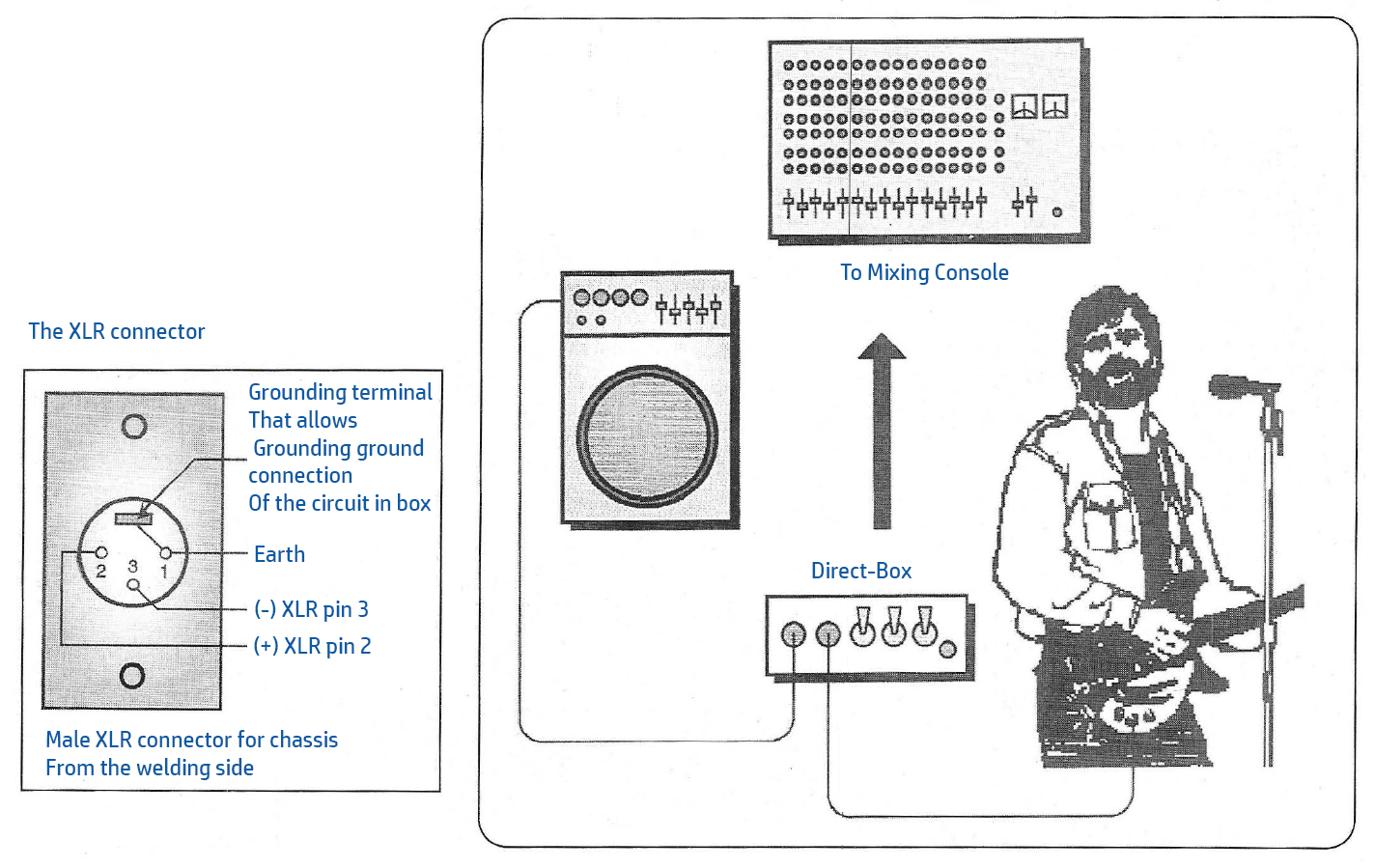
Audio consoles feature a microphone input known as "Phantom," designed to power electrostatic microphones. The XLR microphone connector supplies a few milliamps at 48V, sufficient to power a preamplifier, which is the only active component in the setup.
The device can be powered either through a hidden power supply or a battery. A single 9V battery is adequate for operation, but two batteries in series (18V) provide improved signal output.
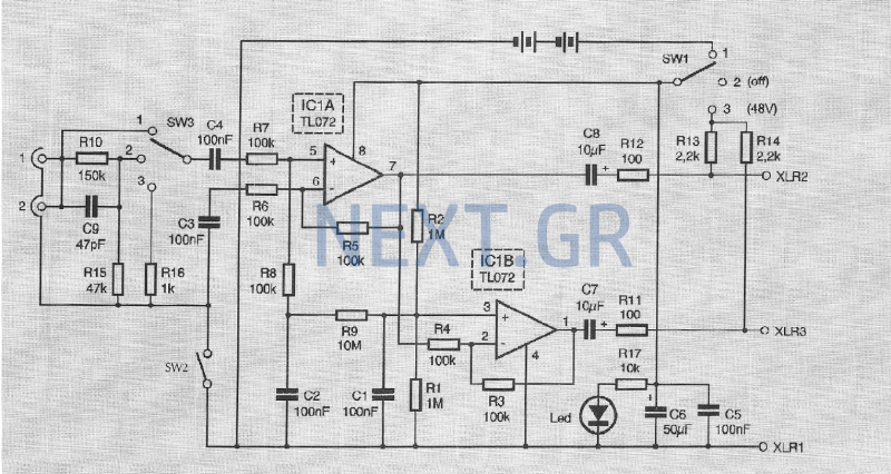
At the input stage, there are two parallel Jack connectors, J1 and J2. The first connector is for the source (e.g., guitar), and the second allows connection to an amplifier. A 3-position attenuator enables the connection of different sources. In position 1, the gain is set to 0dB; in position 2, it is set to 15dB (R10/R15) for electric pianos or synthesizers at line levels; and in position 3, the attenuation is 45dB (R10/R15 and R16) for connecting speaker outputs from amplifiers.
The values of R10 and R16 can be adjusted if necessary, but it is recommended not to decrease the resistance value of R15 (47kΩ), as this would lower the input resistance of the device and could disrupt the parallel connection with the amplifier.
The SW2 switch isolates the ground of the Jack connectors from the grounding of the mixing console, preventing unwanted ground loops that can cause a 50Hz hum.
The amplifier stage features IC1, a differential amplifier with unity gain. The chosen integrated circuit (TL072) is a low-noise dual-power amplifier with high input resistance, low distortion, and reasonable cost. The required Vcc/2 biasing for operation is generated by the R1/R2 voltage divider, which directly biases the IC1b stage, while the biasing for IC1α is provided by the R9 resistor. Capacitors C1 and C2 filter the signals and prevent phase discrepancies between stages. IC1b is configured as a unity gain voltage inverter.
At the output stage, terminals 7 and 1 produce two opposite phase signals of equal amplitude, characteristic of a symmetric output stage. Capacitors C7 and C8 (50V) separate the DC component from the "hidden" power supply, which is then presented on the XLR connector terminals 2 and 3 of the mixing console.
Resistors R13 and R14 allow recovery of the 48V supply if the SW1 switch is set to the 48V position, with filtering provided by capacitors C5 and C6. An electrolytic capacitor primarily disconnects high frequencies, a function assigned to C5.
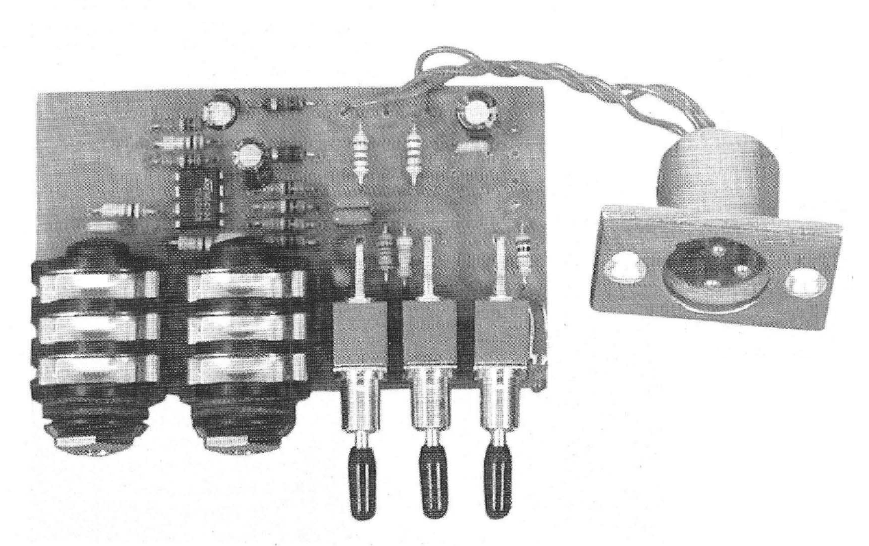
The assembly process should begin with the smaller components. Selecting low-noise (metal film) resistors for the amplification and attenuation stages (R3 to R5, R10, R15, and R16) is advisable for any audio circuit. No adjustments are necessary, as the circuit is designed to function correctly upon initial setup.
Components:
R1, R2: 1MΩ
R3-R8: 100kΩ
R9: 10MΩ
R10: 150kΩ 1%
R11, R12: 100Ω
R13, R14: 2.2kΩ
R15: 47kΩ
R16: 1kΩ
R17: 10kΩ
C1-C5: 100nF
C6: 50μF/50V
C7, C8: 10μF/50V
C9: 47pF
IC1: TL072
SW1, SW3: ON-OFF-ON
SW2: ON-OFF
LED
J1, J2: 6.35mm Jack
XLR male for mountingThe sound is taken from a musical instrument in two different ways. Through a microphone that is placed in place by the instrument amplifier or via a direct connection between the instrument and the mixing console via a direct-box device. The benefits of direct-box versus microphone is that each microphone added to the scene is an additional source of Larsen phenomenon (microphone) phenomenon between microphones and scene back speakers.
The direct signal recording device is less bulky than a microphone that is mounted on a base and allows the connection of classical instruments (guitar) and electronic instruments (electronic piano). Signal recording devices are available in two types. Active and passive. Passive is nothing but a symmetrical line through a transformer, while the active devices, which are the subject of this article, are a symmetrical integrated circuit preamplifier.
The advantage of the passive model is that no power is needed, while the disadvantage is that the embedded transformer limits the bandwidth. The audio consoles offer a microphone input called "Phantom" and are intended to power the electrostatic microphones.
The XLR Microphone Connector offers some mA at 48V, a value that is enough to power a power amplifier, which is also the only active component of the construction. The cradle will be fed either through the "hidden" power supply or via a battery. Only a 9V battery for good operation is sufficient, but two batteries in series (18V) allow for a much better signal output signal.
Entrance Stage
At the input of the device, there are two parallel Jack connectors, J1 and j2. The first one will serve to connect the source (guitar, etc), and the second will allow for the possible connection of the amplifier. A 3-position attenuator allows the connection of different sources. In position 1 the gain is 0dB, in position 2 the gain is 15dB (R10 / R15) to connect electric pianos or synthesizers or line levels, while in position 3 the attenuation is 45dB (R10 / R15 and R16) for Connect the speaker outputs of the amplifiers.
R10 and R16 values can be revised if the levels do not match your own application.
We recommend not to reduce the resistance value of R15 (47kΩ), which would result in a reduction in the input resistance of the device, which should be as large as possible to avoid disturbing the parallel connection of the amplifier.
The SW2 switch allows you to isolate the ground of the Jack connectors from the grounding of the mixing console to avoid a possible ground loop undesirable in the sound because it produces the very undesirable 50Hz buzz.
Amplifier and symmetry
Step IC1 is a differential amplifier with unit amplification. The selected integrated circuit (TL072) is a low-noise dual-power amplifier with high input resistance, low deformation rate and a reasonable cost.
The Vcc/2 polarization required for operation is generated by the R1/R2 voltage divider, which directly polarizes the IC1b stage, while polarization of IC1α is provided by the R9 resistor.
Capacitors C1 and C2 ensure filtering and avoid disagreement between the stages. IC1b has been connected as a unit gain voltage inverter.
Exit Stage
At the output, terminals 7 and 1 have two opposite phase signals and the same amplitude since it is a symmetric output stage. C7 and C8 capacitors (50V) allow the separation of the continuous component ("hidden" power supply) that is displayed on the XLR connector terminals 2 and 3 of the mixing console.
The resistors R13 and R14 allow this 48V supply to be recovered if the SW1 switch is in the 48V supply, filtered by capacitors C5 and C6.
An electrolytic capacitor hardly disconnects the high frequencies and this function is left at C5.
Install the small parts first. If you can select low noise (metal coating) resistors for amplification and attenuation steps (R3 to R5, R10, R15 and R16), this advice applies to any audio circuit.
You do not need to make any adjustments, since the circuit must work from the start.
Components
R1,R2: 1ΜΩ
R3-R8: 100kΩ
R9: 10ΜΩ
R10: 150kΩ 1%
R11,R12: 100Ω
R13,R14: 2,2kΩ
R15: 47kΩ
R16: 1kΩ
R17: 10kΩ
C1-C5: 100nf
C6: 50μf/50V
C7,C8: 10μf/50V
C9: 47pf
IC1: TL072
SW1,SW3: ON-OFF-ON
SW2: ON-OFF
LED
J1,J2: Jack 6,35mm
XLR male for mount
Related Circuits
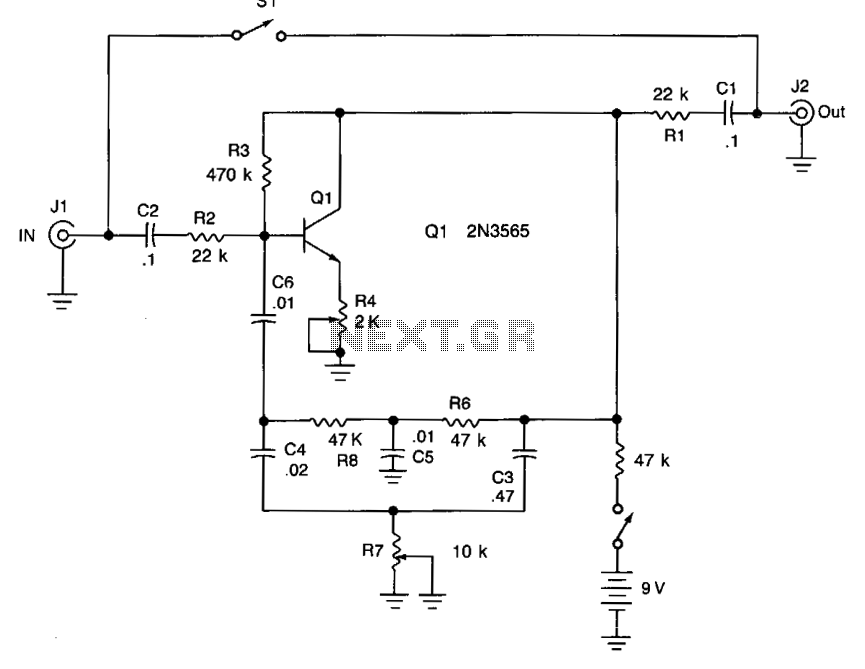
Adjusting potentiometer R7 introduces additional tonal variation from low to high frequencies. To configure the unit, adjust potentiometer R4 until an oscillation or whistle is heard, then reduce R4 until the oscillation stops. The tonal effect can be modified...
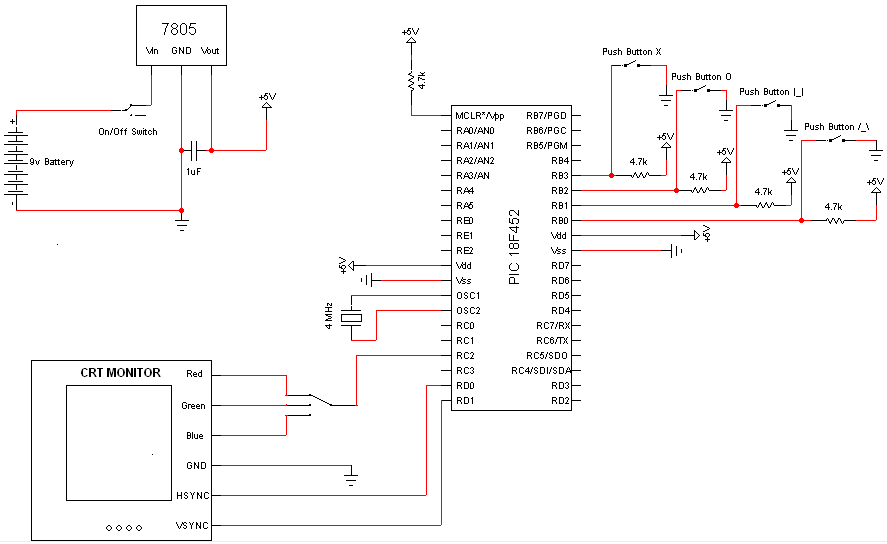
Very few electronic components are required for this project, as the PIC Microcontroller serves as the primary processing unit. The essential components include buttons, switches, and a power circuit, which are straightforward forms of input/output, facilitating an easier understanding...
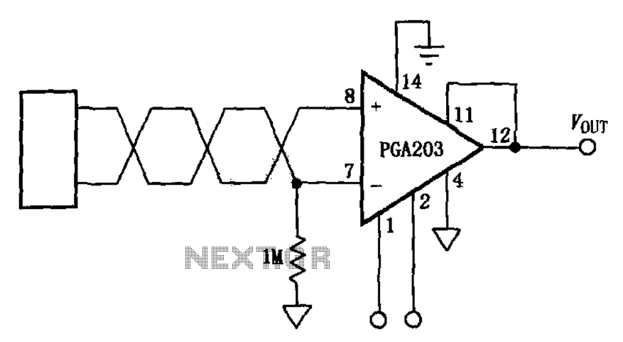
The circuit features a PGA203 programmable instrumentation amplifier. The input signal is applied to the twisted pair inputs of the PGA203, which subsequently amplifies the output signal. It is important to note that the input pins of the PGA203...
This is a grid dip oscillator (GDO) circuit developed by Luigi Falcone. The circuit uses seven plug-in coils that cover the frequency range of 3.0 to 30 MHz. It can be connected to a frequency meter through the coaxial...
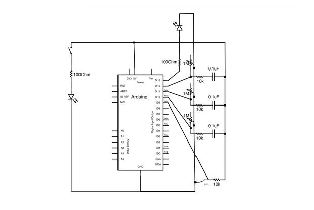
The schematic has been divided into three sections for improved comprehension. The first section illustrates the audio output circuit. This project is designed to output audio. The audio output circuit typically involves several key components that work together to process...

The AD9835 combines the Numerical Controlled Oscillator (NCO), COS Look-Up Table, Frequency and Phase Modulators, and a Digital-to-Analog Converter on a single integrated circuit. With more easy words you can say that this circuit is an oscillator where the...