
Direct PC access through the mounts DB9 connector
The circuit design described involves a straightforward but effective method for interfacing a PC with a mount's stepper motor control system. The use of the MAX232 chip is pivotal for converting RS232 signals from the PC to TTL levels that the stepper motor controller can interpret. The 7805 voltage regulator ensures that the MAX232 operates within its required voltage range, preventing potential damage due to over-voltage conditions.
The schematic should clearly depict the connections between the DB9 connector, the MAX232 chip, and the voltage regulator, emphasizing the importance of correct pin assignments to avoid circuit malfunction. The DB9 connector's pinout must be carefully documented, with specific attention to the power and ground lines, as well as the data lines, to ensure that users can replicate the setup accurately.
Additionally, the design must include safety features, such as current-limiting resistors or fuses, to protect the circuit from overcurrent situations. Proper grounding techniques should be highlighted to minimize noise in the signal lines, which could affect the performance of the stepper motors.
In summary, this modification offers a versatile solution for controlling stepper motors in various mounting applications while emphasizing the importance of careful implementation and testing to prevent damage to both the circuit and the connected equipment.This page presents an alternate option to directly control your mount`s stepper motor board. There is not much difference in terms of stepper control functionality from the original modification as they both allow commands to be sent from the PC directly to the stepper controller board. The difference between the two basically is the number of ele ctronic components required for the mod. The original one requires only three components;the 74HC157 mux chip, a 10k ohm resistor, and a toggle switch which are all soldered on the handcontroller circuit board. The option below does not require you to connect the handcontroller but would require you at least 10 electronic components not including the PCB, serial cables, casing, etc.
The reason why the original mod has lesser components is that it utilizes the rs232-TTL conversion circuitry of the handcontroller while the diagram below would require you to produce the same rs232-ttl conversion on a separate circuit board. In any case these two options are identical in terms of functionality and are presented providing the user two possibilities to control the stepper motors of the mount.
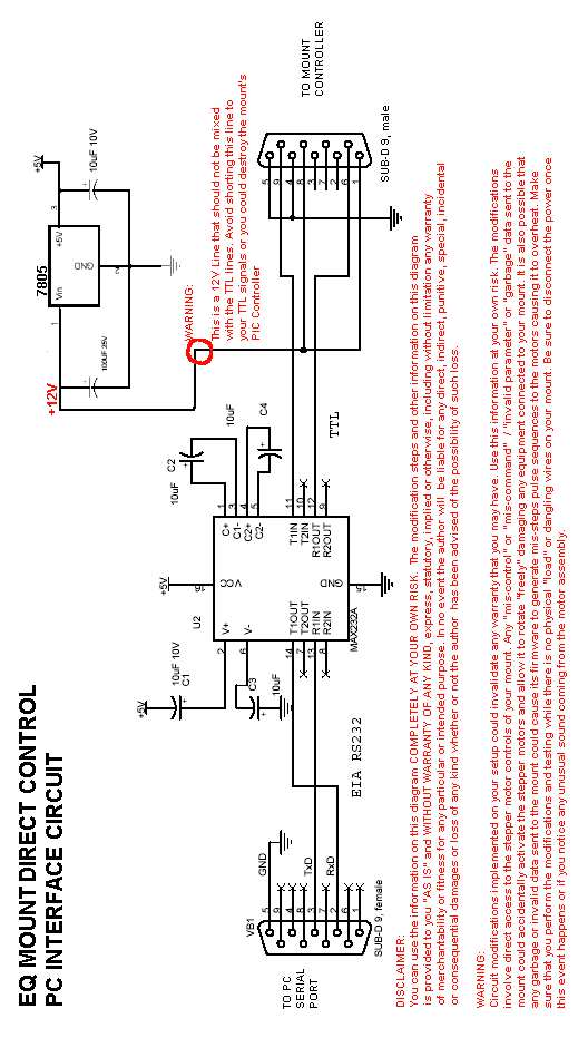
Figure 1 shows a diagram that will allow you to directly connect your PC to the Mount`s DB9 Handcontroller Port. The port contains both the 12V power lines and the two TTL level serial data lines. It allows the user to send the commands from the PC`s serial port to the mount`s handpaddle DB9 port.
The circuit utilizes two major components; a RS232C-TTL converter (MAX232) chip and a 5 Volt voltage regulator (7805) that supplies power to the max232 chip. The 7805 source of power comes from pins 1 and 8 of the mount`s DB9 connector. Extra care should be provided in avoiding these lines to be inerchanged/shorted to the TTL level lines (pins9 and 6).
Pins 5 and 4 are ground pins. Shoestring Astronomy will be producing soon a ready made commercial version of EQDIRECT called EQDIR. This was made possible by Mr. Doug Anderson of Shoestring Astronomy. You can use the information on this site COMPLETELY AT YOUR OWN RISK. The modification steps and other information on this site is provided to you "AS IS" and WITHOUT WARRANTY OF ANY KIND, express, statutory, implied or otherwise, including without limitation any warranty of merchantability or fitness for any particular or intended purpose.
In no event the author will be liable for any direct, indirect, punitive, special, incidental or consequential damages or loss of any kind whether or not the author has been advised of the possibility of such loss. Circuit modifications implemented on your setup could invalidate any warranty that you may have. Use this information at your own risk. The modifications involve direct access to the stepper motor controls of your mount. Any "mis-control" or "mis-command" / "invalid parameter" or "garbage" data sent to the mount could accidentally activate the stepper motors and allow it to rotate "freely" damaging any equipment connected to your mount.
It is also possible that any garbage or invalid data sent to the mount could cause its firmware to generate mis-steps pulse sequences to the motors causing it to overheat. Make sure that you perform the modifications and testing while there is no physical "load" or dangling wires on your mount.
Be sure to disconnect the power once this event happens or if you notice any unusual sound coming from the motor assembly. 🔗 External reference
Related Circuits
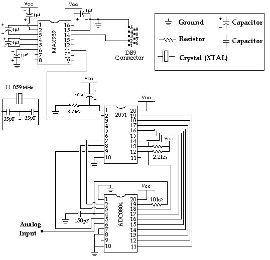
Data Collection - Analog to Digital Conversion and Communicating with a PC through the Serial Port Microcontroller Advanced Kit. The system described involves the process of data collection through analog-to-digital conversion, enabling communication with a personal computer via a serial...
A low-cost continuous wave (CW) superheterodyne receiver operates with a 4.00 MHz intermediate frequency. While there is no automatic gain control (AGC) or RF gain control, the receiver demonstrates good large signal handling capabilities. The design incorporates six bipolar...

The circuit can control the speed and direction of rotation of a series-wound DC motor. Silicon controlled rectifiers Q1-Q4 are arranged in a bridge configuration and are triggered in diagonal pairs. The selection of which pair to activate is...

The INA321/322 is configured to directly drive the capacitive input of an A/D converter. Due to its low output resistance, the INA321/322 can effectively handle high frequency signals and directly drive capacitive loads. The input voltage is amplified by...
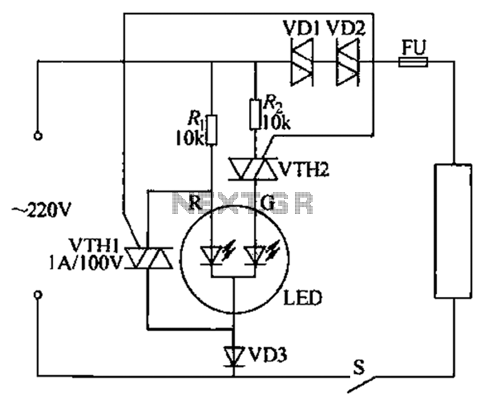
Color light-emitting diodes with different colors can indicate the operational status of electrical equipment, as illustrated in the accompanying figure. The red light-emitting diode (LED) R emits red light when energized, indicating that the 220V power supply is functioning...

The circuit utilizes two CD4001 packages, incorporating eight NOR gates. It operates by receiving pulse streams that are input to an RS flip-flop, producing an output waveform with a variable duty cycle based on the direction of rotation. The...