
Windshield wiper controller
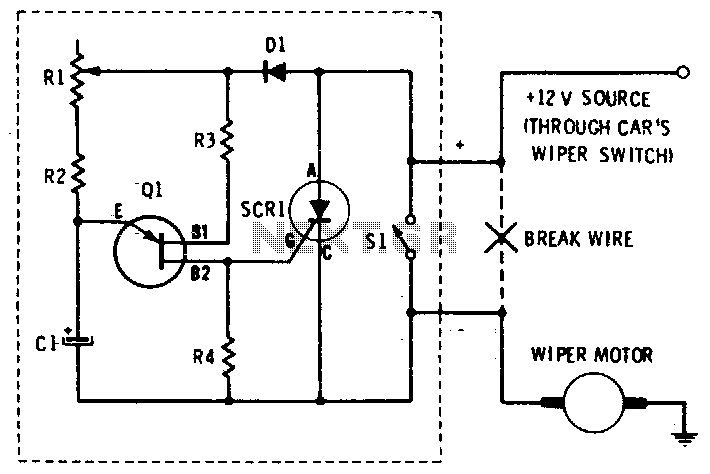
The windshield wiper speed control circuit is designed to offer variable speed adjustments, enhancing the driver's ability to manage wiper operation under different weather conditions. The core of the circuit is the unijunction transistor (UJT), which operates as a free-running oscillator. This oscillator generates a pulse-width modulation (PWM) signal that dictates the timing of the wiper motor's operation.
The UJT is characterized by its ability to produce a continuous oscillation, where the frequency of the oscillation can be adjusted by varying the resistance in the timing circuit. This resistance, typically implemented using a potentiometer, allows for fine-tuning of the wiper speed. The output from the UJT is fed into the gate of a silicon-controlled rectifier (SCR), which functions as the actuator in this system. The SCR is a semiconductor device that can control the power delivered to the wiper motor by varying the phase angle of the AC supply voltage.
As the PWM signal from the UJT varies, it triggers the SCR to conduct for different durations, effectively controlling the average power supplied to the wiper motor. This results in a smooth transition between different speeds, allowing the wipers to operate at a minimum of four sweeps per minute up to their maximum speed. The design is robust and reliable, ensuring that the windshield wipers can be adjusted according to the driver's preference and environmental conditions, thereby improving visibility and safety while driving.This circuit provides complete speed control over car"s windshield wipers. They can be slowed down to any rate even down to four sweeps per minute The controller has two principal circuits: The rate-determining circuit—a unijunction transistor connected as a freerunning oscillator, and the silicon-controlled rectifier which is the actuator. 🔗 External reference
Related Circuits
The Arduino Uno features an ATMEGA328P-PU microcontroller and various additional components on the board. The objective is to program the microcontroller without relying on the Arduino software, utilizing only the essential components. The goal is to develop projects independently...
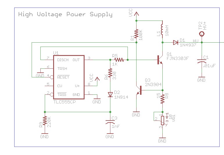
The design involves using a 555 timer as an oscillator in the high voltage power supply section. There is a query regarding the possibility of altering the design to utilize an output from a microcontroller to generate an oscillating...
Foggers used to generate fog and smoke effects operate by heating a special fogger fluid. They consist of a heating element that is maintained at the correct temperature using a thermostat. When the operator wants to generate smoke, they...
This unit provides 2-way IR communications using a numeric keypad and an LCD display. Data is sent and received in ASCII with no regard to what the data means to any particular device. The ASCII data still needs some...
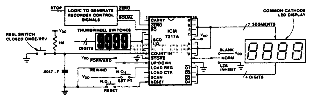
This circuit illustrates various applications of up/down counting for monitoring dimensional position. In the tape recorder application, the LOAD REGISTER, EQUAL, and ZERO outputs are utilized to control the recorder. To ensure the recorder stops at a specific point...
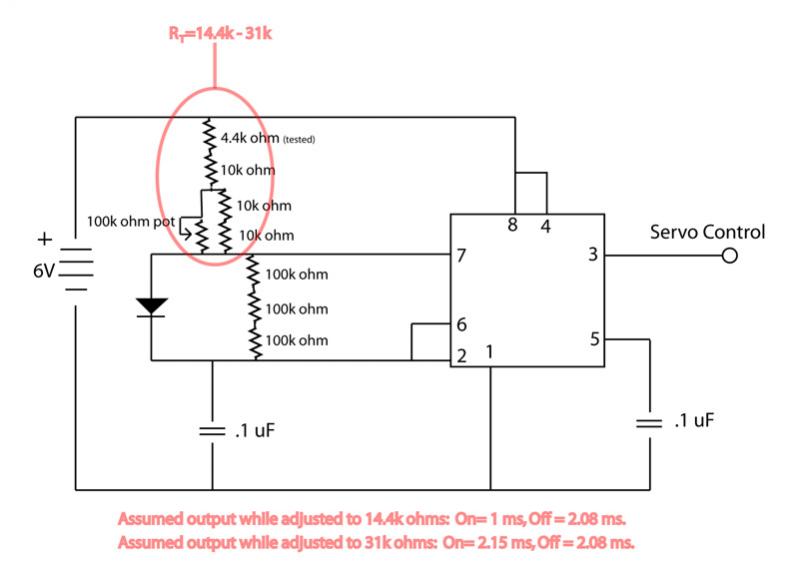
The circuit is not providing the full range of motion for a servo, only achieving approximately 90 degrees. Assistance is requested to review the circuit. To address the issue of limited servo motion, it is essential to analyze the circuit...
Warning: include(partials/cookie-banner.php): Failed to open stream: Permission denied in /var/www/html/nextgr/view-circuit.php on line 713
Warning: include(): Failed opening 'partials/cookie-banner.php' for inclusion (include_path='.:/usr/share/php') in /var/www/html/nextgr/view-circuit.php on line 713