
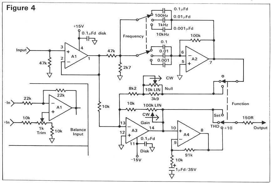
Distortion Analyzer
The pre-distortion circuit is designed to improve linearity in amplifiers by compensating for distortion before it occurs. This circuit typically utilizes a feedback mechanism that adjusts the input signal based on the output signal's characteristics. The single trimmer adjustment mentioned allows for fine-tuning of the circuit to optimize performance for specific applications or component tolerances.
In the context of total harmonic distortion (THD) measurement, the circuit operates in conjunction with a dedicated distortion analyzer. This analyzer employs a notch filter, which is a critical component that effectively eliminates the fundamental frequency from the signal being analyzed. By removing this frequency, the analyzer can focus on the harmonics and noise present in the output, enabling accurate calculations of distortion percentages.
The use of switched frequencies in the analyzer, while a limitation compared to continuously tuned systems, is offset by the affordability and simplicity of the device. Users are required to adjust their sine wave generator to align with the analyzer's frequency settings, which is a straightforward process but necessitates precision to ensure accurate readings.
Overall, this pre-distortion circuit and its associated measurement tools form a practical solution for audio engineers and technicians aiming to enhance the fidelity of their audio systems by minimizing distortion. Proper setup and calibration are essential for achieving optimal results, making the understanding of both the circuit and measurement techniques critical for effective application.The pre-distortion circuit described here is extremely simple (Figure 1) and only requires one trimmer adjustment, though you`ll need an accurate way to measure THD in order to achieve the best results. A dedicated distortion analyzer to help you adjust the linearizer circuit is shown later in this article.
This analyzer has turned out to be one of the most useful little gadgets I have, given its simplicity and incredibly low price. The only thing keeping it from being lab quality is that it uses switched rather than continuously tuned frequencies.
Therefore, you must adjust your sine wave generator to match its frequencies, rather than the other way around. At the heart of any THD meter is a notch filter that can completely remove the original test frequency. After filtering, it is an easy task to measure the harmonics and noise that remain, and relate them to the total signal as a percentage.
It also helps 🔗 External reference
Related Circuits
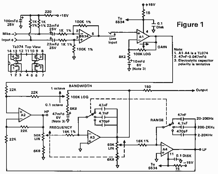
The circuit shown in Figure 1 uses only two ICs, and has a bandwidth that is adjustable from more than one octave down to a tenth of an octave. As shown, the frequency range is 20 Hz. to 20...
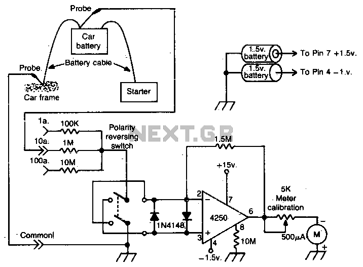
This operational amplifier (op-amp) analyzer is designed to measure the current drawn by any device in a vehicle. It operates by detecting the minute voltage that develops across the battery cables when current flows. To calibrate the unit, the current...
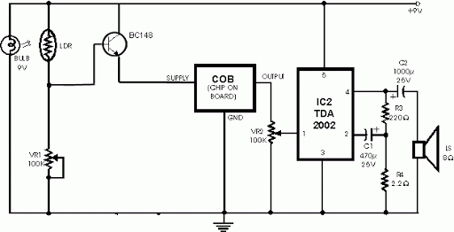
This circuit employs a straightforward method for detecting smoke in the air. It utilizes a bulb as a light source and an LDR (Light Dependent Resistor) as a light detector. When smoke from a fire obstructs the light path...

This complex oscillator circuit utilizes a photocell and a common-mode suppression circuit to achieve a distortion level of 0.0003%. It replaces the lamp in the traditional Wien bridge with an electronic equivalent. The oscillator circuit described is a sophisticated design...
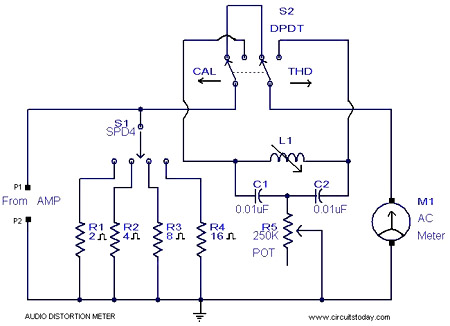
This is a simple 1 kHz audio distortion meter designed to measure the Total Harmonic Distortion (THD) on any load at any output power. The circuit allows for the selection of load impedances of 2, 4, 8, or 16...
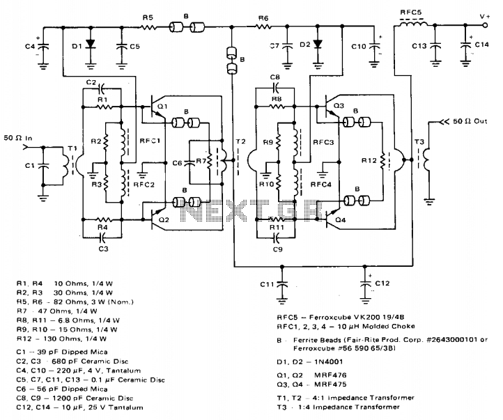
The amplifier achieves a total power gain of approximately 25 dB, utilizing a construction technique that incorporates low-cost components throughout. The MRF476 is rated as a 3-watt device, while the MRF475 delivers an output power of 12 watts. Both...