
LowCost Spectrum Analyzer
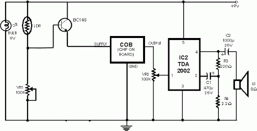
This smoke detection circuit operates on the principle of light interruption. The bulb emits light, which travels towards the LDR. Under normal conditions, the LDR has a specific resistance value that allows it to function within a predefined range of ambient light. When smoke particles enter the light path, they scatter the light, causing a reduction in the intensity of light reaching the LDR. As a result, the LDR's resistance increases, which can be monitored by an electronic circuit configured to trigger an alarm or notification system.
To implement this circuit, a basic schematic can be outlined as follows:
1. **Components Required**:
- A light bulb (incandescent or LED)
- An LDR (Light Dependent Resistor)
- A resistor (to form a voltage divider with the LDR)
- A transistor (for amplification and switching)
- An alarm (buzzer or LED indicator)
- A power supply (battery or DC source)
2. **Circuit Configuration**:
- Connect the light bulb to a suitable power source. The bulb should be positioned in such a way that it directs light towards the LDR.
- The LDR is connected in series with a fixed resistor to form a voltage divider. The junction between the LDR and the resistor will provide a voltage that varies with the light intensity detected by the LDR.
- This voltage is fed into the base of a transistor. The transistor acts as a switch; when the voltage exceeds a certain threshold (indicating a significant change in light intensity due to smoke), it turns on.
- The collector of the transistor can be connected to an alarm system, such as a buzzer or an LED, which will activate when the transistor is turned on.
3. **Operation**:
- Under normal conditions, the light from the bulb keeps the LDR's resistance low, maintaining a stable voltage at the transistor's base.
- When smoke enters the detection zone, the light intensity decreases, causing the voltage at the base of the transistor to drop below the threshold, turning the transistor off and triggering the alarm.
4. **Considerations**:
- It is essential to calibrate the circuit to minimize false alarms from ambient light changes. This can involve adjusting the resistor values or using a more sophisticated light-sensing mechanism.
- The positioning of the bulb and LDR should be carefully considered to maximize the effectiveness of smoke detection while minimizing interference from other light sources.
This circuit is a basic representation of smoke detection technology and serves educational purposes. It is important to note that this design should not replace professional smoke detection systems that are rigorously tested and certified for safety.This circuit uses a very simple approach to detecting smoke in the air. Quite simply, it uses a bulb as a light source, and an LDR (Light Dependent Resistor) as a light detector. As fire smoke comes between the bulb and LDR, the resistance of the LDR changes, which in turn trigger an alarm.
This probably isn`t an ideal approach given that ambient light levels are likely to cause false alarms, however it is an interesting experiment. Just please don`t set any fires while experimenting. And please don`t rely on it as a replacement for a real fire alarm device. 🔗 External reference
Related Circuits
When this circuit is connected to a filter and an oscilloscope, the oscilloscope displays the filter's frequency response. A frequency that sweeps from low to high is applied to a filter. An oscilloscope is triggered by the start of...
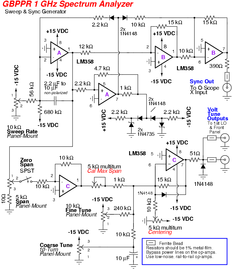
An RF spectrum analyzer is an essential tool for experimenters. The spectrum analyzer project described here is an enhancement of the "Spectrum Analyzer for the Radio Amateur" (Part 2) project by Wes Hayward (W7ZOI) and Terry White (K7TAU), which...
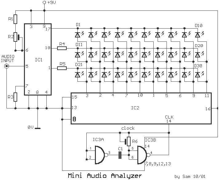
This analyst is a sensitive instrument in the frequency changes and width of an acoustic signal. Thus, the brightness of the LED that turns on each moment is proportional to the signal width, while the color is proportional to...
Most individuals seeking to modify and enhance their Spectrum often focus on the keyboard as a primary area for improvement. However, a straightforward replacement requires opening the computer, which can be discouraging for two main reasons. Firstly, this action...
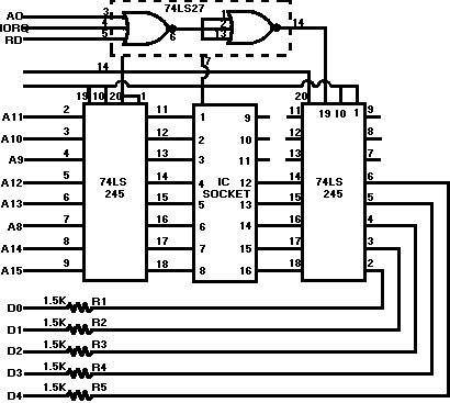
Some time ago, an electronic hobbyist sought to create a logic analyzer. As a DIY enthusiast, a simple yet effective logic analyzer was constructed. Utilizing an old Pentium III laptop equipped with a single LPT port, a search for...
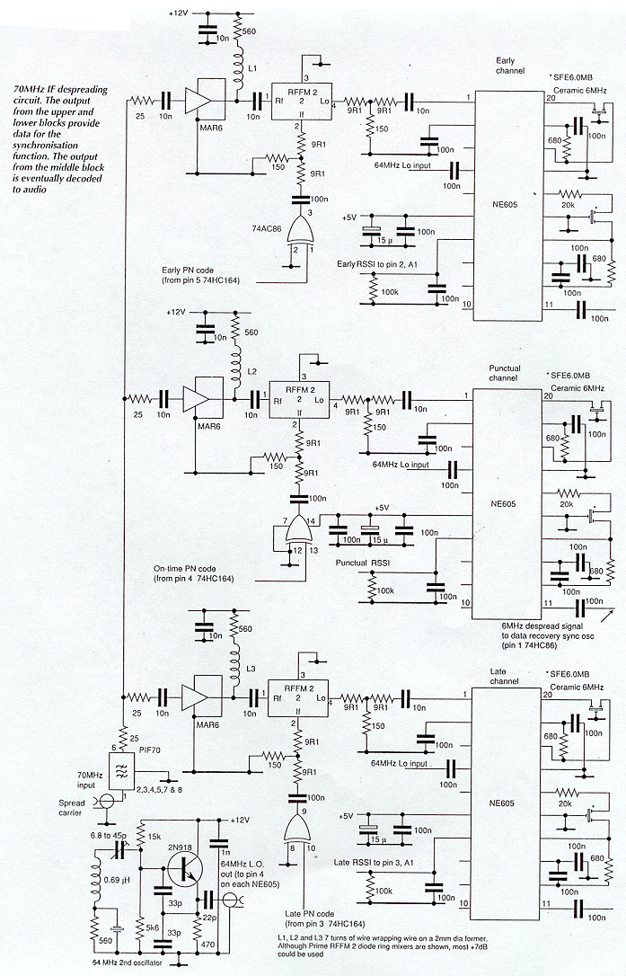
Until recently, spread spectrum techniques were primarily utilized in military applications. Their implementation in GPS and modern cellular phones is paving the way for various civil applications. This article, the first of two parts, explores the technology by detailing...